The Triumph Dolomite Club - Discussion Forum

The Number One Club for owners of Triumph's range of small saloons from the 1960s and 1970s.
It is currently Fri Apr 19, 2024 10:00 pm

All times are UTC+01:00


Post new topic  Reply to topic  [ 226 posts ]  Go to page Previous 112 13 14 15 16 Next
Author Message
PostPosted: Fri Jul 19, 2013 10:11 pm 
What a masterpiece!


Top
   
PostPosted: Fri Aug 02, 2013 3:13 pm 
HI Neil,
Just a picky to let you see how ive fitted my carbon roof
I have welded some thin steel brkts which I will epoxy the roof to
I have made them thin so I can push the roof to the body cut line to get them in the exact position
Image
Then its just a matter of final fettling of roof to get the line cock on
Image
Hope this helps don't know if you have done it a similar way ??
ATB Daz


Top
   
PostPosted: Fri Aug 02, 2013 11:39 pm 
Offline
Future Club member hopefully!
User avatar

Joined: Tue Dec 26, 2006 12:36 am
Posts: 699
Location: Isle of Wight
He hasn't done that bit yet, we're trying to do everything that's easier with no roof first :)

Useful pictures, ta :)


Top
   
PostPosted: Mon Aug 05, 2013 12:48 am 
Offline
Future Club member hopefully!

Joined: Tue Jan 10, 2012 12:39 am
Posts: 517
Just been looking at the build and am very impressed at the work that has gone into it.
Can I mention something that we found in our own (not as good) project some years ago regarding the drivetrain. There are some pictures on page 9 and text referring to the alignment of the drivetrain and it all looks very straight which we found to be a problem. A very straight setup with all the axis in a straight line caused us a vibration problem. It was only cured by deliberately changing the diff nose and gearbox drive flange angles so the propshaft had a small angle to work through. Apparently a perfectly straight system allows any tiny amounts free play to cause vibration. Give it a small angle and it goes away.
I hope you don't find any similar problems but it might be something to bear in mind if you do.

Can't wait to see it on the road.

_________________
Russ Cooper
Dursley
UK


Top
   
PostPosted: Tue Aug 06, 2013 8:25 pm 
Offline
Future Club member hopefully!
User avatar

Joined: Tue Dec 26, 2006 12:36 am
Posts: 699
Location: Isle of Wight
The diff is iirc 2 degrees nose down and it's off to one side (the drive flange is not in the middle of the axle). The gearbox is I think in the middle.


Top
   
PostPosted: Wed Aug 07, 2013 12:49 am 
Offline
Future Club member hopefully!

Joined: Tue Jan 10, 2012 12:39 am
Posts: 517
Quote:
The diff is iirc 2 degrees nose down and it's off to one side (the drive flange is not in the middle of the axle). The gearbox is I think in the middle.
That sounds like you should be OK and won't have the vibration problem we had. Keep up the excellent work!

_________________
Russ Cooper
Dursley
UK


Top
   
PostPosted: Sun Aug 11, 2013 9:13 am 
Offline
TDC Member
User avatar

Joined: Mon Jan 19, 2009 10:46 am
Posts: 298
Location: Leiston, Suffolk
I really like what you have done with the starter motor relocation. It hadn't even occurred to me that it would be straightforward.

I'm designing a header manifold and moving the starter will free up all the room I need. Can you share any more info on how you managed it? What sort of starter, mods to the gearbox adaptor etc.

Ironically, Triumph had the starter on this side of the engine in the six cylinder cars and the bell housing bulge :shock: is obviously still there.

Tom

_________________
Finished with Main Engines and Steering....

1981 1500 HL man/od
1972 Series 3 Land Rover diesel
2007 MX5 Sport
2010 Citroen C1
1993 Gas Gas GT32


Top
   
PostPosted: Fri Aug 16, 2013 7:11 pm 
Sorry, I have been side tracked lately.
Cheers for the pics Darren.

As for the axle as Steve says, it is not as straight as it looks will hopefully not have the problems you had, only time will tell, thanks for the advice.

Tom
The Starter motor is a Brise one with a zetec nose fitted that I Have then machined down to give more clearance to the block. I have had to lightly dress the block as well.
I welded an extension piece onto an ally backplate i had and machined a new hole. Have yet finish modding the adapter plate. Next time I take it out I will take some better pics as I forgot. If you want any more info or dims drop me a pm.


Top
   
PostPosted: Fri Aug 16, 2013 8:32 pm 
Offline
Future Club member hopefully!
User avatar

Joined: Thu Oct 06, 2011 1:13 am
Posts: 3173
Location: The continent
The Dutch way.
Attachment:
tussenp214721021-L.jpg
tussenp214721021-L.jpg [ 115.8 KiB | Viewed 3350 times ]
Attachment:
starter2-M.jpg
starter2-M.jpg [ 75.93 KiB | Viewed 3350 times ]
Jeroen

_________________
Classic Kabelboom Company. For all your wiring needs. http://www.classickabelboomcompany.com


Top
   
PostPosted: Sun Dec 22, 2013 10:30 pm 
Thought it was time I actually did an update.


Image
Found a convenient location for a knock sensor with enough meet to drill and tap the block.


Image
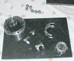
Machined up the oil pump pulley, the oil feed housing & the alternator belt tensioner bracket


Image
Made the bracket for the dry smp pump though this turned out to have to much flex and now has a second fixing point attached to it.

Image
Bracket welded onto the timing chain cover for the dry sump pump

Image
Dry sump pump test fitted, you can also see the alternator half in place which is off Steves supra, but required a bit of machining to give clearance to the oil hoses


Image
Water pump hosing modified to suit the electric water pump.

Image
Water pump fitted in place though it no longer fits there so will need to make some new brackets for it.

Image
My fisrt stab at a prototype sump.
Image

Image
My second stab at a prototype sump, this is pretty close to how the final version will be but in ally and with all the gaps filled in.

Image
sump trial fitted & scavange pipes made up ready for welding.

Image
belts and associated components all fitted up.
Image

Image
Decided it was time to try something new and inspired by Darren so purchased all the kit to make resin infusion components.
Image

Image
First attempt at making a plug, this subsequently got scrapped along with the first attempt at making a mold.

Image
Second attempt at a mold being split from the part in this pic.

Image
Component being made.

Image
Component removed from the mold.

Image
component (half an airbox) cleaned up and fitted to the car, this was only ever meant as a test and trial piece and has quite few problems, the next one will be much better and the final versions in carbon.


Last edited by Neil907 on Wed Sep 17, 2014 10:26 pm, edited 1 time in total.

Top
   
PostPosted: Mon Dec 23, 2013 1:26 am 
Offline
Future Club member hopefully!
User avatar

Joined: Sun Oct 21, 2012 11:15 pm
Posts: 822
this car is going to be mental! :shock:

_________________
1980 Dolomite Sprint Track Day Car....KLJ 895W. now redtopiffied :P

viewtopic.php?f=19&t=23031

Volkswagen Golf MK3 Gti....R301UUJ. RIP 22-5-13
Volkswagen Golf MK4 TDGTI 150 MM53VNT Sold 7-8-17
BMW 320d Coupe M-Sport YL08 XBZ with factory fitted Performance Pack - Sold 22/05/21
BMW 330d Touring M-Sport WN63 XPY - best daily ever

Proud TDC Member!


Top
   
PostPosted: Mon Dec 23, 2013 7:06 pm 
Offline
TDC Member
User avatar

Joined: Mon Jan 19, 2009 10:46 am
Posts: 298
Location: Leiston, Suffolk
How will you wire in the knock sensor Neil? I've wondered how to integrate one into Microsquirt for a while.

_________________
Finished with Main Engines and Steering....

1981 1500 HL man/od
1972 Series 3 Land Rover diesel
2007 MX5 Sport
2010 Citroen C1
1993 Gas Gas GT32


Top
   
PostPosted: Mon Dec 23, 2013 7:29 pm 
On the Vems 2 wires just go straight back to the ECU, I think I used a piece on twin core screened.


Top
   
PostPosted: Tue Dec 24, 2013 9:45 am 
Nice one Neil ,
Looking really good
You will be making lots of carbon parts now its addictive LOL
Forget the infusion mesh and peel ply
This is what you want believe me
So much easyer to work with as its fused together
http://www.ecfibreglasssupplies.co.uk/p ... uply2.aspx
Keep the updates coming I was getting withdrawal ,


Top
   
PostPosted: Tue Dec 24, 2013 8:06 pm 
Offline
Future Club member hopefully!
User avatar

Joined: Tue Dec 26, 2006 12:36 am
Posts: 699
Location: Isle of Wight
Not too much carbon stuff to make, doors, bonnet, boot and roof for my TVR, and might maybe find time to do a handful of bits of Dolly :)


Top
   
Display posts from previous:  Sort by  
Post new topic  Reply to topic  [ 226 posts ]  Go to page Previous 112 13 14 15 16 Next

All times are UTC+01:00


Who is online

Users browsing this forum: No registered users and 108 guests


You cannot post new topics in this forum
You cannot reply to topics in this forum
You cannot edit your posts in this forum
You cannot delete your posts in this forum
You cannot post attachments in this forum

Search for:
Jump to:  
Powered by phpBB® Forum Software © phpBB Limited