Tonight's job was to do a leakdown test. I have to admit that I haven't done this before and despite doing a lot of reading up on the subject I'm not 100% familiar with it so I'll go through what I did, followed the instructions of course and let Jeroen or anyone comment.
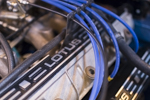
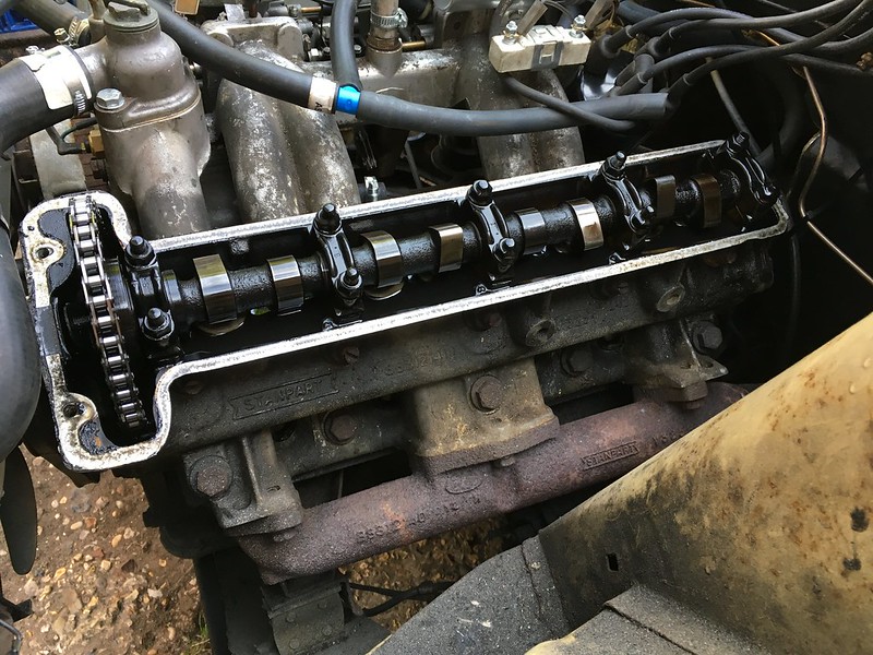
I removed the cam cover so I could easily see when each cylinder was at TDC on the compression stroke, I also removed the expansion tank cap, dipstick and air cleaner. The reason I did this was so I can hear for any air leaking past the inlet valves (through the carbs), exhaust valves (from the pipe), rings (dipstick) and the head gasket (bubbles in the expansion tank).
Everything looks ok under there, a bit dirty but the cam is in good condition.
Set the engine to TDC on number 1 cylinder on its compression stroke.
I set the air pressure on the compressor to 60 psi (the instructions said anywhere between 7-100 psi).
Screwed the adaptor hose into number 1 cylinder
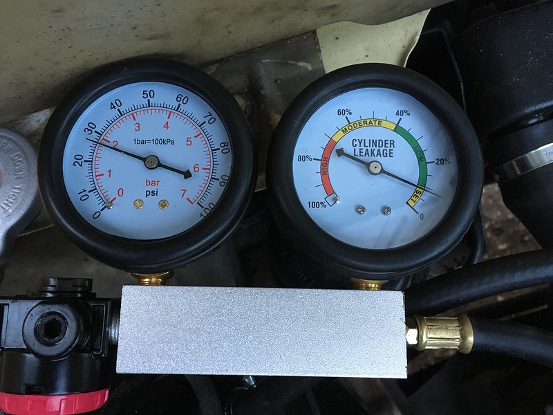
Connected the unit to the air supply and set the cylinder leakage to 0
Connected the adaptor hose to the measuring unit, noted the results.
I did the same for each cylinder in the firing order 1-3-4-2
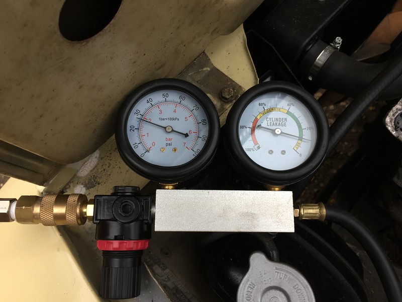
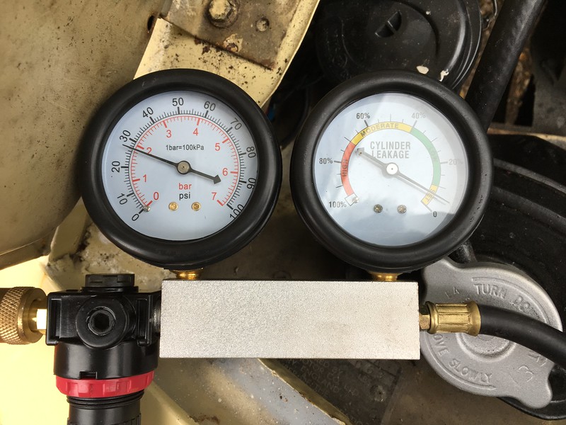
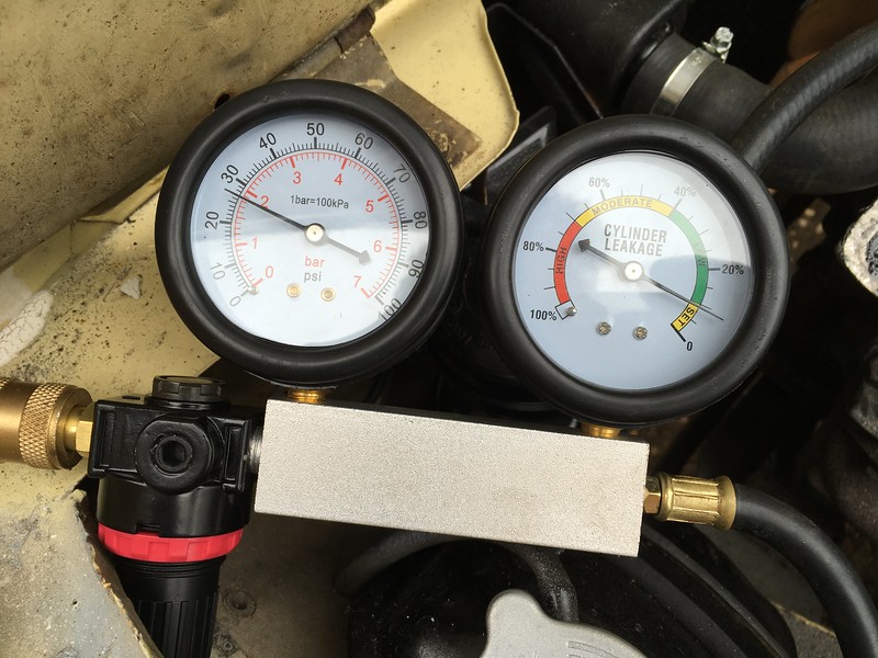
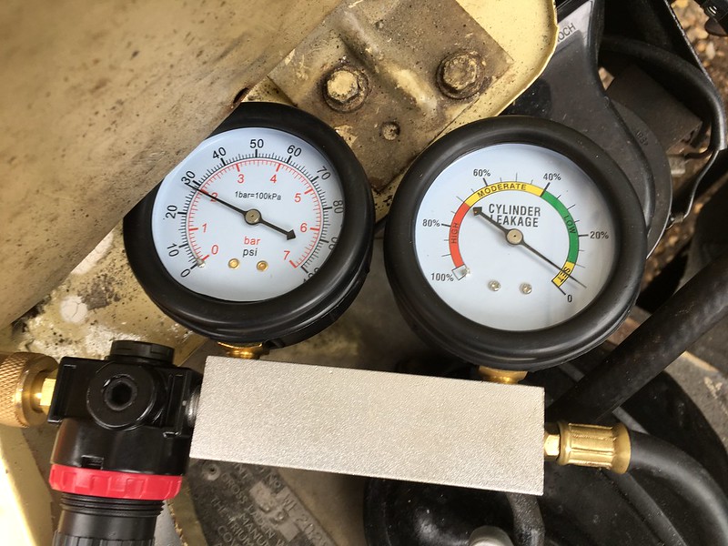
These are the results.
Cylinder 1
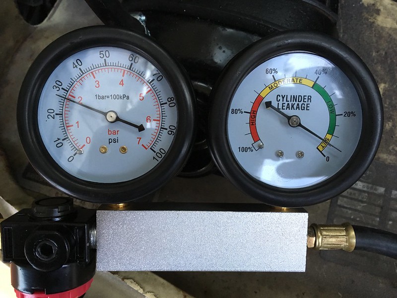
Cylinder 3
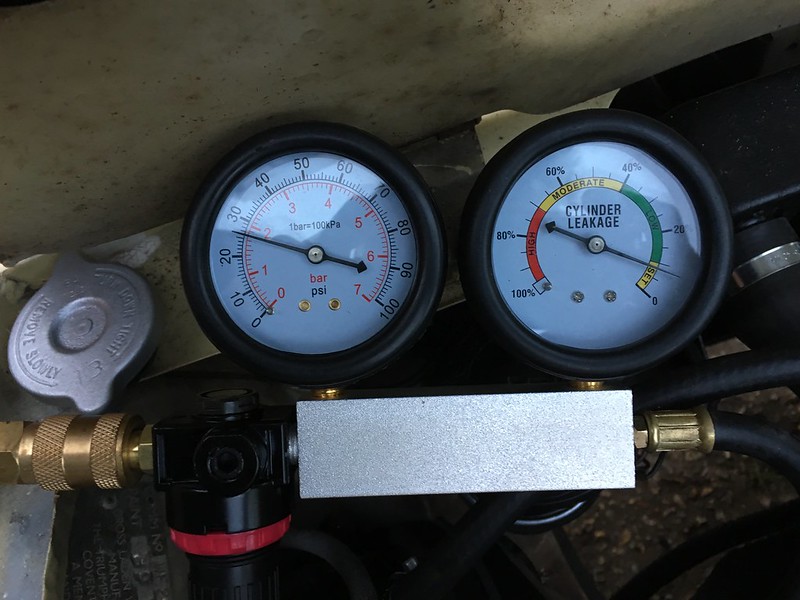
Cylinder 4
Cylinder 2
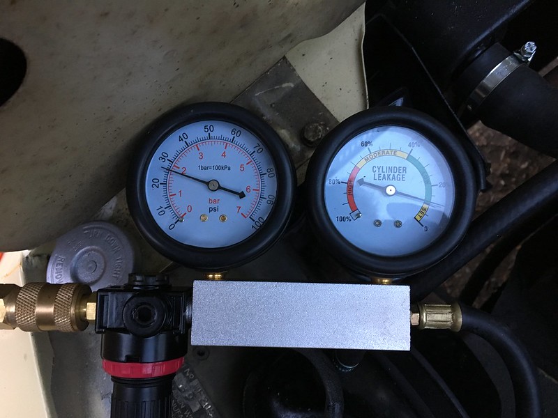
If I have done everything correctly the the readings look very good indeed and show that the internal condition of the engine is sound. I did this twice and got the same readings, the inlet pressure looks consistent as well. Jeroen, what do you think. Have I done this correctly?