a bit of thread necromancy, but maybe this could be put into the faq section or "how to"
I recently made up a new voltage stabiliser for a friend in Hobart, whose stag was showing very high temperature readings.
here 'tis
Attachment:
 vs-01.jpg [ 68.03 KiB | Viewed 3702 times ]
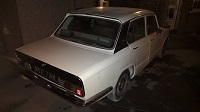
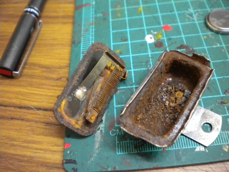
the original unit, the male spade connection is the voltage going in, dark green. The female spade connector is the light green wire, stablised connection.
Attachment:
 vs-02.jpg [ 67.97 KiB | Viewed 3702 times ]
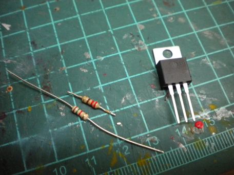
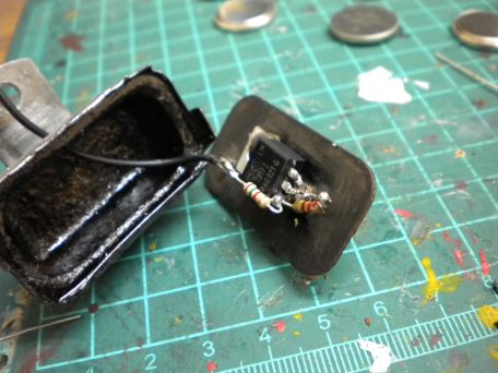
the components used, LM317T variable voltage regulator and two resistors used to set the voltage.
Attachment:
 vs-03.jpg [ 71.13 KiB | Viewed 3702 times ]
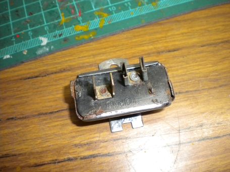
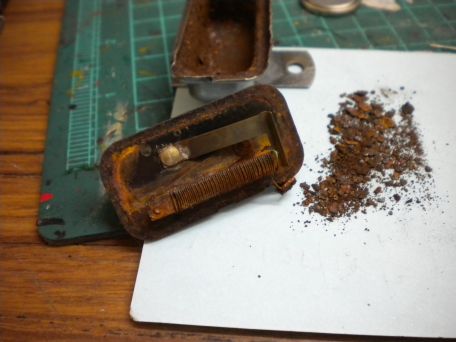
inside the old case. Apart from the rust, it works through a make break switch, which is similar to an old fashioned indicator flasher. The wire wrapped around the metal leaf heats it, which causes it to expand and break the contact, it then cools and comes back into contact. This happens many times a second (you can hear them when they are working, they vibrate). The duty cycle determines what voltage they give. There is an adjustable set screw on top of the case for fine tuning the output voltage.
Attachment:
 vs-04.jpg [ 62.93 KiB | Viewed 3702 times ]
more rust
Attachment:
 vs-05.jpg [ 69.95 KiB | Viewed 3702 times ]
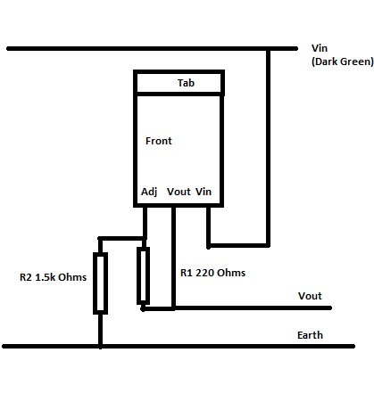
new circuit.
Attachment:
 LM317T Stabiliser circuit.jpg [ 21.85 KiB | Viewed 3702 times ]
The tab on top of the regulator is the output (as well as the middle leg) so it has been soldered directly onto the female spade connection inside the case. The right leg (Vin) has been likewise soldered to the male spade connector. The resistors go between Vout and Adj (left leg, 220 Ohms) and Adj and ground (1.5 KOhms), this gives a Vout according to:
Vout = 1.25(1 + R2/R1)
in practice the resistors have a tolerance and there is extra voltage due to the current drawn through R2, so a bit of trial and error is needed if you want perfection.
Attachment:
 vs-06.jpg [ 67.88 KiB | Viewed 3702 times ]
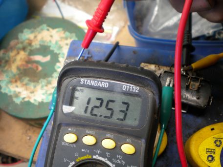
this is the battery voltage, note the red multi-meter probe on the battery positive terminal
Attachment:
 vs-07.jpg [ 70.34 KiB | Viewed 3702 times ]
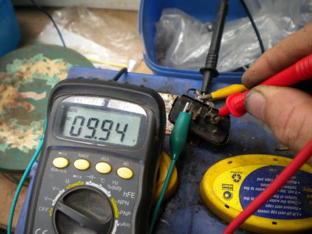
This is the stabliser output, 9.94V is pretty damn close to the 10V needed, so I left it at that.
One extra connection though. The old stabliser had a pinch connection sandwiched between the top and the case which acted as a ground for the heating element. I figure this was hit and miss, so have drilled a small hole in the side of the case and run an earth lead, terminated in an eyelet, so when the unit is screwed down, you'll need to ensure this is earthed. When you clip the top on, just make sure the internal leads aren't shorting, plenty of room in the case so shouldn't be a problem.
I've also just made up 3 more stabilisers using another regulator chip, specifically designed for the job, an L2610,
http://www.datasheetcatalog.org/datashe ... 5f0zcy.pdf
one for my sprint, one for Thomas's sprint, one for the stag and I ran out of regs so left the best of the originals for the 1850 "donor"
so, there appear to be several ways to skin this cat,
stew's original LM2940T 10Volt Transistor
a variable regulator LM317T set up to deliver 10V (easily pushes through 1.5A)
a L7810 which is a fixed 10 volt reg, if you can find 'em
a L2610 which has 0.5A output and is another dedicated 10V reg
any of which will work fine and none require any extra filtering capacitors.
stu