The Triumph Dolomite Club - Discussion Forum

The Number One Club for owners of Triumph's range of small saloons from the 1960s and 1970s.
It is currently Wed Apr 24, 2024 5:52 am

All times are UTC+01:00


Post new topic  Reply to topic  [ 196 posts ]  Go to page Previous 1 2 3 4 514 Next
Author Message
PostPosted: Sun Nov 04, 2012 7:54 pm 
Offline
Future Club member hopefully!

Joined: Tue Sep 25, 2012 2:08 am
Posts: 388
Location: Christchurch, New Zealand
Few of us have all the necessary skills and experience to undertake projects such as those featured in this section of the Forum.

I have spent some time over the last few months looking at other restoration projects featured on this forum and marvelling at what others start with, what they do and then following it through to the finished project. Sometimes photos are posted to show some particular happening or feature and sometimes those of us who follow that particular restoration pick up detail which has not been clear to us before.

I have found MikeyB’s thread on the restoration of VA969 Mike’s Early Sprint Restoration to be particularly helpful. Mike’s photos are superb and those looking through this thread seeking information on where or how to, or what ever would do well to read this thread. The same goes for reading straylight (Stu’s) thread Sprint Restoration in South Australia. I can relate to Stu’s thread for like Stu I am many thousands of miles away from the source of supply which is available to most of you. So like Stu it is often a question of making do, restoring what I have, rather than opting for the fitting of some new old stock (NOS) which might be available in the UK.

I have spent these past few days “dressing” if that is the right word, the engine bay before I carry out the last “up and under” manoeuvre and bring the engine and subframe assembly in from underneath. I am waiting to bolt on the exhaust pipe with connects to the engine manifold. It has been sent away for coating in a high temperature ceramic finish which both preserves the pipe work and which should help to lessen the radiation of heat into the engine bay itself. I have had the engine and gearbox in (and out) twice now as I have checked on various detail and then removed the assembly so that I can continue to work in the engine bay. It is no more than a 20 minute job to wheel the whole engine assembly in and lower the body over it and at the same time bolt up the subframe and bottom shock absorber mounts.

Last evening Stu provided me with the dimension so that I can now fabricate a new bulkhead mounted exhaust heat shield. That is one of the last jobs I have to do to complete the work in the engine bay itself. I had earlier asked for these dimensions on this forum. It is little queries like these that highlight the problems we have here and which also confirms the success of this forum.

I cannot go and look at someone else’s car for there are none accessible locally and nor can I expect someone to slip me one in the mail so that I can copy it. So I am filled with envy when I read Mark’s thread Operation Orange – 1980 Sprint restoration. This is another restoration thread which is proving to be particularly useful to me. Oh what luck Mark had to be able to start with a new body shell and then to be able to do things like order a new wiring loom from a local supplier. It is also another thread where others are contributing and offering up their wisdom gained from previous experience which I find so helpful.

But still there are little details which leave me baffled. Like for instance where exactly is the main wiring loom routed around the accelerator pedal. Does it sit above it; does the pedal sit behind it? I pore over other people’s photographs looking for the clues.

Mark is fitting headlamp relays. I have done so too, for having owned two 2.5PI’s both fitted with halogen headlamps it makes sense to use relays to ensure all those electrons light the night sky and not fry the switch on the steering column.
Attachment:
20121013-3596Pw Headlamp relay mounts.jpg
20121013-3596Pw Headlamp relay mounts.jpg [ 74.69 KiB | Viewed 2588 times ]
Here then is my solution. A couple of nice little fused relays mounted alongside the radiator where I was able to break into the existing wiring harness and fit the necessary plugs so that it “looks” more like something that might have been fitted in the factory.
Attachment:
20121105-3630Pw Headlamp relays.jpg
20121105-3630Pw Headlamp relays.jpg [ 92.39 KiB | Viewed 2590 times ]
It is about, as you can see, making do with what is available to us down here.


Last edited by Robert 352 on Mon Nov 05, 2012 10:00 pm, edited 1 time in total.

Top
   
PostPosted: Mon Nov 05, 2012 10:12 am 
Offline
Future Club member hopefully!

Joined: Tue Oct 03, 2006 9:45 pm
Posts: 11179
Location: Middlesex
that is sooo neat and a very nice looking job....

But...

In the UK I cant see the relays lasting long there as the road salt gets past the radiator....so I'd go for higher up the wing by the batterry...or even have longer wires and stick it by the original fuse box.

But in NZ you will be fine....and I say again...lovely neat job.....and loving this thread in general.


Jonners

_________________
Note from Admin: sadly Jon passed away in February 2018 but his humour and wealth of knowledge will be fondly remembered by all. RIP Jonners.


Top
   
 Post subject: Robert......
PostPosted: Mon Nov 05, 2012 6:24 pm 
Offline
TDC Member
User avatar

Joined: Thu Aug 09, 2007 1:22 pm
Posts: 6481
Location: Caithness, Scotland
You have what looks like an early 1850 radiator fitted (angled RH top spout).
It has the same capacity as a Sprint version (1.2 litres) but has fewer fins so won't cool as much.
I have not tried an 1850 radiator on a Sprint to see if there is a difference.


Ian.

_________________
TDC Forum moderator
PLEASE help us to maintain a friendly forum,
either PM or use Report Post if you see anything you are unhappy with. Thanks.


Top
   
 Post subject: What is salt used for?
PostPosted: Mon Nov 05, 2012 7:35 pm 
Offline
Future Club member hopefully!

Joined: Tue Sep 25, 2012 2:08 am
Posts: 388
Location: Christchurch, New Zealand
Jonners has mentioned the word “salt”. We only use salt on our chips – with a dash of tomato sauce as well. So I have visions of British roads covered in salt added to which are added lashings of tomato sauce. Must make one hell of a mess of the windscreen on everybody’s car.

Jonners is right of course in his comments about where to place/hide the relays and I originally debated placing the relays in behind the right hand front suspension turret somewhere very close to the clutch reservoir. Well out of harms way. I ruled out placing them beside the battery for when I bought this car that is where the previous owner had attached relays for horns, headlamps and other paraphernalia. It looked like a plate of spaghetti gone wrong. As you can see here.
Attachment:
198904-16 35Ptw Dolomite Sprint engine bay.jpg
198904-16 35Ptw Dolomite Sprint engine bay.jpg [ 63.58 KiB | Viewed 2629 times ]
So I opted for the position shown for another reason as well. I have fitted a new feed to the headlamps, brown wire to match the standard colour code, and by fitting the relays where they are it keeps the lead back to the plug on the battery lead very short. And the wiring from the relays to the headlamps is kept short too. Indeed I did not have to alter the existing wiring loom substantially other to break into it about where the relays sits. Its about getting all those electrons to where they are supposed to go.

It is tucked up out of the way and pretty well protected from the “wind and rain”! I am sure it will be fine here in this country.

Ian has also raised an interesting comment about the radiator shown in my earlier posting. Now that has got me puzzled and I will now have to spend a few more evenings poring over the images on a number of threads on the Forum looking for something that will give me a clue as to what the sprint radiator should look like.

There is a remote possibility that the one shown in my photo is an early 1850 radiator for the car which was cut to provide the back end for this restoration was, I suspect, an early 1850 for the engine had Stromberg carburettors fitted to it.

That poses a question which only I should be able to answer and that is where did the radiator from that car go? Or equally and even more puzzling, where is the original radiator out of my car?

Do keep making these observations for they help me with my reassembly of the car.

Robert


Top
   
PostPosted: Mon Nov 05, 2012 9:38 pm 
Offline
Future Club member hopefully!

Joined: Tue Sep 25, 2012 2:08 am
Posts: 388
Location: Christchurch, New Zealand
For weeks I have now been trying to figure out exactly where the wiring harness should sit around the steering column and through the firewall into the engine bay. The harness has been sitting roughly in position from long before I put the roof lining in and installed everything in the boot. But there was always something not quite right about the position up in the front of the car.

However MikeyB’s restoration and the photos on his thread have come up trumps again. I was studying the pictures on page 18 of his thread, VA969 Mike’s Early Sprint Restoration, and spotted the clue I needed – see the picture relating to the refitting of the pedals. I had positioned the break in the harness where the feed comes out to the steering column on the right hand side of the two P clips. Mike’s picture sort of shows it fitted on the left of that P clip. So in moving mine to that position as shown here;
Attachment:
20121106-3632Pw Internal wiring harness.jpg
20121106-3632Pw Internal wiring harness.jpg [ 91.03 KiB | Viewed 2601 times ]
everything fell into place. The yellow arrows show the column harness coming off between the two clips.

The harness around and below the brake servo mount and the accelerator pedal moved into its correct position and in doing so the worry which I had that the harness might catch on the accelerator pedal disappeared. I have used a cable tie to hold it back temporarily until I place the instruments back in the dash.
Attachment:
20121106-3634Pw Internal wiring harness.jpg
20121106-3634Pw Internal wiring harness.jpg [ 79.76 KiB | Viewed 2599 times ]
And then finally I clipped the harness in the engine bay into its correct position noting that in Mike’s pictures that the feed off to the gearbox came off at about the position shown by the yellow arrow.
Attachment:
20121106-3635Pw engine bay wiring harness.jpg
20121106-3635Pw engine bay wiring harness.jpg [ 91.79 KiB | Viewed 2599 times ]
So Mike, another public vote of thanks for the work which you did a couple of years ago. And to those who will follow later and be looking at these and other pictures about “how” to do something, may I suggest you keep looking through these various thread for its like a treasure hunt. Someone before you has faced the same problem you are trying to overcome. The answer will be somewhere here on this Forum.

Let me finish here with a comment about the colour of the green shown in the photos. The tint may not look correct but please note that the photos you are looking here have been taken in low light, at I might add, a very high ISO camera setting which accounts for the grainy type appearance, and taken with a flash. I have not compensated for the use of the artificial flash light but can assure you that when the car is seen under normal light it matches the tin of original Brooklands Green paint that came with the car – as supplied by BL back in 1975.

On to the next task then…..

Robert


Top
   
PostPosted: Mon Nov 12, 2012 9:26 pm 
Offline
Future Club member hopefully!

Joined: Tue Sep 25, 2012 2:08 am
Posts: 388
Location: Christchurch, New Zealand
Progress slowed a little over the past couple of weeks for I have been waiting for some spares to arrive from the UK. They arrived in the mail today. So now I can proceed to bolt the gearbox onto the engine in preparation for the final up and under manoeuvre which will see the whole engine and subframe assembly moved into the car from below.

I had some problems with my gearbox recently. I lifted it up onto the bench in order to roll it onto its side to check and clean the overdrive filters. It rolled away from me and dropped to the floor breaking the top cover. However I have located a replacement cover locally and the gaskets I need to refit it and the overdrive filter cover came in the parcel received in the mail today.

So progress has been limited to finishing off the engine bay with the construction of a bulkhead exhaust shield out of some stainless sheeting. It is a little wider than the factory fitment and covers the area of the cut out in the bulkhead padding. If it proves to be too large then I will modify it to fit.
Attachment:
20121112-3639Pw Sprint engine bay.jpg
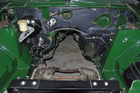
20121112-3639Pw Sprint engine bay.jpg [ 106.34 KiB | Viewed 2454 times ]
The two unpainted brackets sitting on top of the suspension turrets are the attachment points for lifting the body during the up and under manoeuvre. Note too that the subframe fitted in this photo, is what I call a mule, for it is an 1850 subframe and it is there for with the front wheels attached and with the whole car sitting on four castored dollies the car can be pushed around the workshop.

The downpipe which attaches to the exhaust manifold has been sent away to be coated with a high temperature ceramic coating and is expected back this week. When that has been fitted then the whole engine assembly will be ready to put back into the car.

I located a source of T2500 7/16 diameter front wheel studs and have turned down the diameter of the head behind the splines so that they fit into the front hubs. When fitted they are marginally shorter than the 3/8 studs but I do not expect this to be a problem.

I have started fabricating a rear axle hub puller for this will allow me to fit the larger studs to the axle hubs. There is some comment on the Forum elsewhere about being able to do all this without removing the rear hub assembly but I might as well fabricate up the tool at this time and do it properly for Murphy’s Law says that I will have to change the oil seals which sit behind the hubs at some stage. It will be used again sometime I am sure.

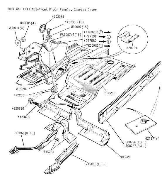
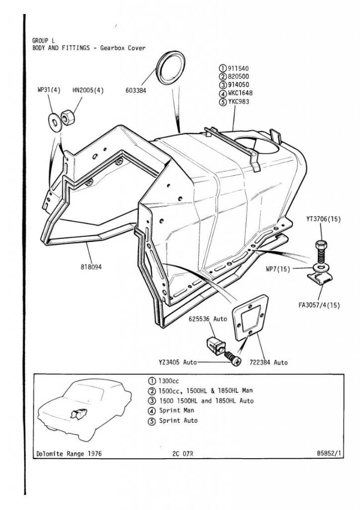
The next job will be to fabricate a gearbox tunnel cover to suit the Sprint gearbox. My original cover has rusted badly but I have a couple of 1850 covers which I think can be modified. The hole for the gearlever is further back on the Sprint. However I am unsure how the plastic console unit which sits around the gearlever is attached to the rear of the cover. I would be most grateful if someone could post a picture of this area of a gearbox tunnel cover showing this detail for although I have trawled through various threads on the Forum I cannot see the detail I want to see.

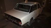
On Friday I drive south to Dunedin, some 240 miles away, to have a look at a cache of what has been described as Dead Dolomites. At least four 1850’s of which I think three are automatics, all are parked around a house. The owner had the intention of restoring a couple but has given up and they are to be sent off for scrapping. I hope to rescue one at least which I can then use for parts. One of the four is fitted with Stromberg carburettors so will be a fairly early car and the fourth, a manual, is fitted with an overdrive gearbox.

Perhaps though I could rescue one as my next project although I fancy working on something quite different.


Top
   
PostPosted: Tue Nov 13, 2012 12:33 pm 
Offline
Future Club member hopefully!
User avatar

Joined: Tue Oct 03, 2006 5:52 pm
Posts: 7562
Location: Halifax, West Yorkshire
Robert, may I suggest that you restore the early auto? Ideally, all the autos should be saved. The 1850 autos quite rare but to find 3 in the same place in NZ is quite something. The transmission tunnel should have spire clips or something so that you can screw the gear lever surround on to the tunnel. When I get home (posting this reply from work) I'll post the relavant page from the parts catalogue then you'll see what I mean. In the meantime I found this from Mad Mart's website.
Image

_________________
Toledo Man

West Yorkshire Area Organiser & forum moderator
Meetings take place on the first Wednesday of the month at 8.00pm at The Old Brickworks, Wakefield Road, Drighlington, Bradford, BD11 1EA

1972 Dolomite 1850 auto (NYE 751L - Now for sale)
2003 Volvo XC90 D5 SE (PX53 OVZ - The daily driver)
2009 Mercedes-Benz W204 C200 CDI Sport (BJ58 NCV - The 2nd car)
1991 Toyota Celica GT (J481 ONB - another project car)
Former stable of SAY 414M (1974 Toledo), GRH 244D (1966 1300fwd), CDB 324L (1973 1500fwd), GGN 573J (1971 1500fwd), DCP 625S (1977 Dolomite 1300) & LCG 367N (1975 Dolomite Sprint) plus 5 Acclaims and that's just the Triumphs!

Check my blog at http://triumphtoledo.blogspot.com
My YouTube Channel with a bit of Dolomite content.

"There is only one way to avoid criticsm: Do nothing, say nothing and BE nothing." Aristotle


Top
   
PostPosted: Tue Nov 13, 2012 6:58 pm 
Offline
Future Club member hopefully!

Joined: Tue Oct 03, 2006 9:45 pm
Posts: 11179
Location: Middlesex
The crucial sprint specific bit is the ring that holds the geasrtick inner rubber bellows style gaiter to the tunnel. Its held by 4 small self tappers into spire clips on the edge of the aperture for the stick on the tunnel. The tray then go0es over this and has 3 screws again into spire clips on some rivitted or spot welded supporting brackets...

Early spriints didnt have the tray...so Mikey B's thread wont show this.

Jonners

_________________
Note from Admin: sadly Jon passed away in February 2018 but his humour and wealth of knowledge will be fondly remembered by all. RIP Jonners.


Top
   
 Post subject: Gearlever console/tray
PostPosted: Tue Nov 13, 2012 7:56 pm 
Offline
Future Club member hopefully!

Joined: Tue Sep 25, 2012 2:08 am
Posts: 388
Location: Christchurch, New Zealand
Thanks for those comments fellows.

I have the crucial bits, for that I can be thankful. That is the rubber bellows and its holding down ring. And the spire clips are still in place on the very rusty cover I have so that fixes both the position of the hole and the clips for me. My car VA10113DLO has the tray and from what I can see it was screwed through the carpet with two screws at the front of the tray directly into the tunnel for it did not have the little bracket shown on the left arrow here.
Attachment:
20121114Ptw Gearbox cover.JPG
20121114Ptw Gearbox cover.JPG [ 23.56 KiB | Viewed 2324 times ]


But it is this attachment on the right arrow which has me a little puzzled. It is not there (or was never there).

If push comes to shove I shall fabricate a little up-stand of some sort and attach it – screw it to the cover and bring it up through or around the edge of the hole that will be cut in the carpet. And then screw the tray to that. Its function will be to hold the tray about level I guess. But it can be done once the tunnel and carpets are all in position. A little dressing job once the car is mobile.

Had a bit of a disaster late yesterday. In bolting the gearbox to the adaptor ring I stripped one of the threads in the adaptor ring itself. A bit of an “Oh bother” moment. I was tightening all the bolts and nuts with a torque wrench and pulling them up ever so carefully as well and this one bolt felt soft even with 10 ft/lbs on it – half what the book says to tighten it to.

So I have stripped the ring off and will get some thread inserts fitted today. There were stripped threads on the head when I pulled the car apart so I imagine whoever has worked on this car before me had never heard of a torque wrench or had mixed his fittings around and screwed a bolt in that was too long for the hole.

Little things which are sent to try our patience. But hey I am getting good at throwing that 40kg gearbox around, and developing the art of sliding it onto/into the clutch without putting too much load on the gearbox input shaft.

Robert


Top
   
PostPosted: Wed Nov 14, 2012 12:25 pm 
ah, the joys of helicoiling stripped threads. Good luck.

Nice documentation Robert, enjoying the read, thanks.

stu


Top
   
PostPosted: Wed Nov 14, 2012 7:46 pm 
Offline
Future Club member hopefully!

Joined: Tue Oct 03, 2006 9:45 pm
Posts: 11179
Location: Middlesex
One bell housing bolt?

I'd have just stuck some epoxy metal on the bolt head stuffed it down the hole and left it at 5lb foot to set. There are 8 or so more to do the job and the dowle takes the torque.

But its your car and you would always have known....:-) When I "did" my box 20 years ago I had one of the 4 bolts shear on the input shaft cover.....that was a git to fix...
and I nearly left that one....but the thought of taking it all out again if the oil seal leaked was just too much for me.
An excellent machinist where I worked slot drilled it out for me...:-)

Jonners

_________________
Note from Admin: sadly Jon passed away in February 2018 but his humour and wealth of knowledge will be fondly remembered by all. RIP Jonners.


Top
   
PostPosted: Wed Nov 14, 2012 9:48 pm 
I wouldn't worry too much about a few stripped threads in the adapter. Mine has about 2 stripped/missing and 1 weak and it's fine...


Top
   
PostPosted: Wed Nov 14, 2012 11:06 pm 
Offline
Future Club member hopefully!
User avatar

Joined: Tue Oct 03, 2006 5:52 pm
Posts: 7562
Location: Halifax, West Yorkshire
Here is the same part in the post-76 parts catalogue:
Image

_________________
Toledo Man

West Yorkshire Area Organiser & forum moderator
Meetings take place on the first Wednesday of the month at 8.00pm at The Old Brickworks, Wakefield Road, Drighlington, Bradford, BD11 1EA

1972 Dolomite 1850 auto (NYE 751L - Now for sale)
2003 Volvo XC90 D5 SE (PX53 OVZ - The daily driver)
2009 Mercedes-Benz W204 C200 CDI Sport (BJ58 NCV - The 2nd car)
1991 Toyota Celica GT (J481 ONB - another project car)
Former stable of SAY 414M (1974 Toledo), GRH 244D (1966 1300fwd), CDB 324L (1973 1500fwd), GGN 573J (1971 1500fwd), DCP 625S (1977 Dolomite 1300) & LCG 367N (1975 Dolomite Sprint) plus 5 Acclaims and that's just the Triumphs!

Check my blog at http://triumphtoledo.blogspot.com
My YouTube Channel with a bit of Dolomite content.

"There is only one way to avoid criticsm: Do nothing, say nothing and BE nothing." Aristotle


Top
   
PostPosted: Thu Nov 15, 2012 4:46 am 
Offline
Future Club member hopefully!

Joined: Tue Sep 25, 2012 2:08 am
Posts: 388
Location: Christchurch, New Zealand
I am afraid Jonners is right. His comments echo my feelings. If I do not repair the stripped threads now it will be one of those little niggles which will annoy me for ever and a day. So I have called in a few favours today and the job has been done.

Two thread inserts fitted this morning for the princely sum of $10 or 5 pounds in your language. So the adaptor plate will be bolted back on shortly. It is so easy to do when the engine is sitting on the subframe out of the car so that is not a problem in that sense. I was just annoyed with myself for stripping the threads in the first place.

I am travelling for the next couple of days so there will not be any work done on the Sprint until early next week. While I am away I will now looking at four automatic 1850's. But I would be interested to hear comments as to why they are worth saving? When my personal preference would be for the manual overdrive option. I am certainly not in a position to save all four and if I save one it will have to be very tidy with good internal trim. And of course for not a great deal of money! There must have been quite a significant proportion of the Dolomites imported here as automatics for I have come across a number of others as well.

Robert


Top
   
PostPosted: Fri Nov 16, 2012 11:37 am 
Offline
Future Club member hopefully!

Joined: Tue Oct 03, 2006 9:45 pm
Posts: 11179
Location: Middlesex
As has been said eslewhere the dolly 1850 auto is more that the sum of the parts. The torque converter match to the engine is very good and the 3.27 diff gives relaxed cruising. It was the best small auto available in its day....

But I'd agree a manual o/d one is more desirable...just.

What amuses me about the sprint tunnel is that the removable rubber bung is still the wrong side for the box filler plug. Its ok for an 1850 but why change the top bit for the Sprint gearbox and not do the bung as well? Weird and makes refilling a sprint box in situ a nightmare....

Jonners

_________________
Note from Admin: sadly Jon passed away in February 2018 but his humour and wealth of knowledge will be fondly remembered by all. RIP Jonners.


Top
   
Display posts from previous:  Sort by  
Post new topic  Reply to topic  [ 196 posts ]  Go to page Previous 1 2 3 4 514 Next

All times are UTC+01:00


Who is online

Users browsing this forum: No registered users and 64 guests


You cannot post new topics in this forum
You cannot reply to topics in this forum
You cannot edit your posts in this forum
You cannot delete your posts in this forum
You cannot post attachments in this forum

Search for:
Jump to:  
Powered by phpBB® Forum Software © phpBB Limited