The Triumph Dolomite Club - Discussion Forum

The Number One Club for owners of Triumph's range of small saloons from the 1960s and 1970s.
It is currently Thu Apr 18, 2024 11:47 am

All times are UTC+01:00


Post new topic  Reply to topic  [ 69 posts ]  Go to page Previous 1 2 3 4 5 Next
Author Message
PostPosted: Sun Jan 30, 2022 4:30 pm 
Offline
TDC Member

Joined: Sun Mar 16, 2008 2:52 pm
Posts: 2304
Quote:
How to re-install UKC2538 – Bypass Connector Tube? Another nuisance question....

This is the 1-1/4” pipe that exits from the bottom of the thermostat housing and connects to the top of the water pump cover.

I am confused by the Repair Operations Manual:

30.15.15 – Inlet Manifold Gasket, Refitting
Step 12 – Carefully install a new connecting pipe via the thermostat housing dome, ensuring that it is pushed downwards to the limit of its travel.

30.15.02 – Inlet Manifold Assembly, Refitting
Step 17 – Carefully install a new connecting pipe via the thermostat housing ensuring that it is pushed downwards to the limit of its travel.

Both of these instructions (with a minor editorial variation), make it sound like one pushes the UKC2538 tube downwards within/through the thermostat housing from the top of the housing, until the tube bottom enters the port on the water pump housing. But...it is physically (dimensionally) impossible to do this “via the thermostat housing”. The connector tube can only be seated into the housing from below.

Was there a design change from what the R.O. Manual describes? To me it looks like the lower end of the connector tube has to be first positioned in the water pump housing port, and then the bottom of the thermostat housing (with the entire intake manifold assembly) need to be pushed down onto the top end of the connector tube.

Furthermore, why do both instructions state that a new connecting pipe needs to be installed? (This is just an academic question since I do have a new UKC2538.) The 1-1/4” pipe hardly looks like it can fail. Surely just replacing the top and bottom o-rings on the connecting pipe would be sufficient normally.

I get nervous when the R.O. Manual makes no sense to me.
Hi Mike, Yes, you are quite right. There was a design change. The early 1850s, and probably the Sprints as well, have a water-transfer tube as a 1-piece construction with a metal water tube enclosed with an overall rubber casing with built-in O-rings. This is 156875. See photo.
And hence the reference to replacing the whole thing.
The early 1850 workshop manual also says to replace this version in the water-pump housing and then refit the inlet manifold over the top. It looks like the change was in about 1974 when the 3 part water transfer tube was introduced, as a stainless steel tube and 2 replaceable O-rings.
Here's one I cleaned up earlier.
This is UKC 2538 + 2 x TRS1114 O-rings.
They do need a lot of cleaning up though and yes, they are inserted through the thermostat housing, but I've done it both ways with a smear of Blue Hylomar on each O-ring.
Good luck with the refitting,
Tony.


Attachments:
156875 UKC2538.jpg
156875 UKC2538.jpg [ 84.77 KiB | Viewed 794 times ]
Top
   
PostPosted: Sun Jan 30, 2022 10:13 pm 
Offline
Future Club member hopefully!
User avatar

Joined: Wed Dec 08, 2021 5:57 pm
Posts: 60
Location: Aiken, SC USA
Steve – I followed up on your suggestion and cleaned up the bottom of the thermostat housing where the UKC2538 connecting pipe is supposed to transit. That did not change my being unable to install UKC2538 down through the housing (there was not much surface crud to remove), but it did reveal the cause of my befuddlement: a significant dimensional change which makes installation of the pipe up from the bottom a must, rather than down through the thermostat housing, an impossibility.

After a lot of fussing around with my point-and-shoot, I was able to visibly capture where the dimensional change occurs. The green arrow shows the point of greatest constriction in the thermostat housing, below which is the larger dimension and furthest point that the pipe can be successfully inserted from below.
==>
Image

I took a new UKC2538 prior to installing the new o-rings on it (hence at its smallest outer diam) to show the maximum extent that the pipe can be inserted from below. It can only be inserted about 5/8”, leaving the remaining 5/8” of the pipe sticking out the bottom of the housing. Yes, it looks a bit cocked, but that is only because I have the old (exceeding grungy) UKC2538 wedged holding the new piece in place so that I can shoot the photo.
===>
Image

I also shot a photo looking down into the housing with the pipe inserted from the bottom as far as it can go before encountering the “ledge” highlighted by the green arrow in the first photo. If that is as far as it can travel upwards, certainly the uninstalled o-ring would make it even more constrained and actually should seal quite nicely under the “ledge”.
===>
Image

OK, so why can't I just stick the connecting pipe down through the thermostat housing as the R.O. Manual says repeatedly? Well, Tony you hit the nail on the head with reference to a design change in 1974. Plus with your observation of the early 1850 manual saying that the connecting pipe should be first inserted into the water pump housing and then the intake manifold being pushed down over the pipe (that is, the pipe must be inserted into the bottom of the thermostat housing). The Sprint R.O. Manual I quoted from seems to apply only to the situation after the 1974 design change.

The final clue is that this particular Sprint, VA7337DL, had a build date of 18 April 1974, which was probably prior to the design change. Thus like 1850, like Sprint.

_________________
Current keeper of “Project PFJ”.
I was “SCMike” in a previous life on this Forum.


Top
   
PostPosted: Mon Jan 31, 2022 8:25 am 
Offline
TDC Member
User avatar

Joined: Wed Nov 15, 2017 3:35 pm
Posts: 957
Location: Filey, North Yorkshire
To echo what others have said, those link pipes are a b1tch. On the 1850 I found the main issue was the o-ring seals moving/rolling during installation, I found the suggestion of lubricating them with some sealant very very helpful. Helps them slide in without moving and then helps them seal as it sets. If I remember rightly I had 2 or 3 goes at it the first time I took the manifold off the 1850.

_________________
Image


Top
   
PostPosted: Mon Jan 31, 2022 1:08 pm 
Offline
Future Club member hopefully!
User avatar

Joined: Wed Dec 08, 2021 5:57 pm
Posts: 60
Location: Aiken, SC USA
Quote:
To echo what others have said, those link pipes are a b1tch. On the 1850 I found the main issue was the o-ring seals moving/rolling during installation, I found the suggestion of lubricating them with some sealant very very helpful. Helps them slide in without moving and then helps them seal as it sets. If I remember rightly I had 2 or 3 goes at it the first time I took the manifold off the 1850.
I will certainly be using sealant on the o-rings. Would blue Hylomar L be appropriate? I used that as thread sealer for the new 1/2” BSP heater hose adaptor that I installed into the new 12-vane water pump cover.

Also would it make sense to do a 2-step process for the install? That is, first apply the sealant only on the o-ring at one end of the link pipe, insert that lower end into the water pump cover, ensure that the pipe is precisely vertical, and then wait several hours for the sealant to fully set. Only then, apply the sealant to the other o-ring and carefully install the intake manifold over this upper end of the pipe. Perhaps the first step would result in a “locked in” link pipe at the pump cover end, with the pipe less likely to shift as the intake manifold is pushed atop the pipe for the second step? Or is that over-thinking things?

I note your 2 to 3 goes at it to do the install properly. I plan to do a couple of dry runs of the install (sans o-rings and sealant) to ensure that I understand how everything fits together before doing the for-real install.

_________________
Current keeper of “Project PFJ”.
I was “SCMike” in a previous life on this Forum.


Top
   
PostPosted: Mon Jan 31, 2022 1:52 pm 
Offline
TDC Member
User avatar

Joined: Wed Nov 15, 2017 3:35 pm
Posts: 957
Location: Filey, North Yorkshire
Quote:
Quote:
To echo what others have said, those link pipes are a b1tch. On the 1850 I found the main issue was the o-ring seals moving/rolling during installation, I found the suggestion of lubricating them with some sealant very very helpful. Helps them slide in without moving and then helps them seal as it sets. If I remember rightly I had 2 or 3 goes at it the first time I took the manifold off the 1850.
I will certainly be using sealant on the o-rings. Would blue Hylomar L be appropriate? I used that as thread sealer for the new 1/2” BSP heater hose adaptor that I installed into the new 12-vane water pump cover.

Also would it make sense to do a 2-step process for the install? That is, first apply the sealant only on the o-ring at one end of the link pipe, insert that lower end into the water pump cover, ensure that the pipe is precisely vertical, and then wait several hours for the sealant to fully set. Only then, apply the sealant to the other o-ring and carefully install the intake manifold over this upper end of the pipe. Perhaps the first step would result in a “locked in” link pipe at the pump cover end, with the pipe less likely to shift as the intake manifold is pushed atop the pipe for the second step? Or is that over-thinking things?

I note your 2 to 3 goes at it to do the install properly. I plan to do a couple of dry runs of the install (sans o-rings and sealant) to ensure that I understand how everything fits together before doing the for-real install.
I'd be hesitant about doing it in 2 stages, if the sealant on the lower ring sets and then the assembly is moved during the upper part install then the seal might be lost? But then I might be over-thinking it too. I used a very thin smear of RTV sealant on the rings on my successful attempt, but did it all "at one go".
Sadly I only found out success/failure when the coolant system came up to pressure.... which means a few bits to remove to get back at it - better if you get it right first time!
I think the main things are: take it slowly, feel for the rings fitting/shifting, watch of anything "not quite right". If you aren't 100% happy, take it apart, clean it, try again.

_________________
Image


Top
   
PostPosted: Tue Feb 01, 2022 2:19 pm 
Offline
TDC Shropshire Area Organiser

Joined: Sun Aug 21, 2011 5:12 pm
Posts: 7040
Location: Highley, Shropshire
Sorry to have given you what appears to be a bum steer!

I knew the early 1850s had this lip, but wasn't aware it also applied to very early Sprint's too! Every day a school day!

In fact it's not long since I did this on my own series 1 car VA 10245DLA, built in early 75 and still carrying it's original motor. But this is obviously later than the change point as it slipped in and out from the top like a charm, saving me a lot of sweat! This car has a Davis-Craig electric water pump and the bypass is a purpose made brass one that is designed to run without a thermostat and only has a pinhole in it. This let me screw a long self tapper into the pinhole and ease it out without even going near the manifold bolts. A couple of new O rings and a smear of grease and job done!

Steve

_________________
'73 2 door Toledo with Vauxhall Carlton 2.0 8v engine (The Carledo)
'78 Sprint Auto with Vauxhall Omega 2.2 16v engine (The Dolomega)
'72 Triumph 1500FWD in Slate Grey, Now with RWD and Carledo powertrain!

Maverick Triumph, Servicing, Repairs, Electrical, Recomissioning, MOT prep, Trackerjack brake fitting service.
Apprentice served Triumph Specialist for 50 years. PM for more info or quotes.


Top
   
PostPosted: Tue Feb 01, 2022 7:32 pm 
Offline
Future Club member hopefully!
User avatar

Joined: Wed Dec 08, 2021 5:57 pm
Posts: 60
Location: Aiken, SC USA
Steve - yes, the “early” Sprint has been a fun learning experience for me as to its “special” features. I greatly appreciate the help provided through this Forum. The TDC is an invaluable resource for those of us in far off places. I am happy to now be identified as “TDC Member” rather than “future…hopeful” in my Forum boilerplate. It only took four weeks for International First Class Mail to deliver my membership application.

_________________
Current keeper of “Project PFJ”.
I was “SCMike” in a previous life on this Forum.


Top
   
PostPosted: Wed Feb 02, 2022 12:22 am 
Offline
TDC Shropshire Area Organiser

Joined: Sun Aug 21, 2011 5:12 pm
Posts: 7040
Location: Highley, Shropshire
Another peculiarity of the "early" Sprints was that the long alternator bolt had to be fitted from the front, it wouldn't go in from the back because the water pump cover interfered with it. So you had to take the radiator out to remove the alternator! Later models adressed this faux pas and made the bolt fittable from the rear.

It occurred to me that with fitting the 12 vane pump and changing the cover, you might now be able to correct this while you have it in bits!

Steve

_________________
'73 2 door Toledo with Vauxhall Carlton 2.0 8v engine (The Carledo)
'78 Sprint Auto with Vauxhall Omega 2.2 16v engine (The Dolomega)
'72 Triumph 1500FWD in Slate Grey, Now with RWD and Carledo powertrain!

Maverick Triumph, Servicing, Repairs, Electrical, Recomissioning, MOT prep, Trackerjack brake fitting service.
Apprentice served Triumph Specialist for 50 years. PM for more info or quotes.


Top
   
PostPosted: Wed Feb 02, 2022 12:55 pm 
Offline
Future Club member hopefully!
User avatar

Joined: Wed Dec 08, 2021 5:57 pm
Posts: 60
Location: Aiken, SC USA
Steve,

Some time ago, I installed a rebuilt alternator and had no difficulties. I guess that Mad Mart made the bolt switch during his 2009 restoration. I didn’t even realize that I had dodged this bullet on the early Sprint alternator fitment.

During all this water pump adventuring, I have been taking the name of Triumph design engineers in vain. After all, why would anyone think it a remotely good idea to go to all the devilish complexity of an in-block water pump when one could just hang it on the front of the block, like it was always done? But I just read on a US TR7 forum that it was all the fault of the Swedes! The slant-4 was developed to serve both SAAB and Triumph (which I knew) with the Swedes requiring a FWD transverse installation, for which there was no transverse space for the usual simple water pump design (which I didn’t know). Since the Swedes were ponying up significant development funds and were going to purchase their engines from Triumph, we ended up with this great “Heath Robinson” design. Perhaps all this is well known, but I just learned that I have been blaming the wrong party.

Mike

_________________
Current keeper of “Project PFJ”.
I was “SCMike” in a previous life on this Forum.


Top
   
PostPosted: Tue Feb 08, 2022 1:42 am 
Offline
Future Club member hopefully!
User avatar

Joined: Wed Dec 08, 2021 5:57 pm
Posts: 60
Location: Aiken, SC USA
Just realized that I was spreading misinformation in the posting immediately above. The SAAB 99 was FWD, but (oops) its engine was definitely not transverse. Upon further looking at a scale drawing of the 99’s longitudinal engine layout, it looks to me that the clutch/transmission also occupying the same space under the bonnet was the packaging problem. The only available real estate was to bury the water pump in the block. And weren’t the earlier FWD Triumphs faced with the same space constraints? So that TR7 forum posting I referenced earlier may have just been urban legend, and unfairly blames the Swedes.

_________________
Current keeper of “Project PFJ”.
I was “SCMike” in a previous life on this Forum.


Top
   
PostPosted: Tue Feb 08, 2022 9:23 pm 
Offline
TDC Shropshire Area Organiser

Joined: Sun Aug 21, 2011 5:12 pm
Posts: 7040
Location: Highley, Shropshire
It's true the Saab motor (initially 1509cc, half a Stag V8) was developed in partnership with Triumph. In fact, it appeared in the first Saab 99s a good 3 years before the (by then 1854cc) slant 4 appeared in the 72 Triumph Dolomite.

Its also true that the Saab features a reverse longitudinal (but still canted at 45 degrees) fitment that brings the timing case (and the water pump, were it fitted in the normal manner) extremely close to the bulkhead. So you'd have reason to believe the pump fitment was a design criteria imposed by Saab to get round a logistics problem.

If it WAS, Saab realized and corrected the error almost immediately. I've never seen an early 1509cc 99, so I don't know what the timing case end of the engine looks like or how the alternator is driven. But I OWNED and became intimately acquainted (had to replace the timing chain and tensioner) with these parts of a 1975 Saab 99 2 litre Combi Coupe. Somewhere around 73-4 the Saab motor developed into a 2 litre 8v (TR7 spec?) still a reversed longitudinal design and crucially, by the time my 75 model was built, had a full house of auxilliary drive components at the timing cover end, pulley, belt, alternator AND a belt driven water pump. And YES adjusting the fanbelt was a nightmare and water pump access was severely limited. But it was there and all the better for it.

My own opinion is that the blame lies squarely with Triumph. Don't forget the slant motor was developed from the Stag V8. Now envisage the timing case end of every V8 ever, the timing cover ends up pierced by large water galleries from each bank of the block with the single, centrally mounted, belt driven water pump feeding both ways to each bank. Now it gets really complex cos the Stag V8, unlike most American designs of the time, has chain driven overhead cams and the chains take up SO much space. Suddenly, the jackshaft driven water pump makes a whole lot of sense!

The fact that Saab (who had no intention of making a V8 version) ditched the shaft driven pump so quickly (virtually as soon as they were making the engines themselves, rather than buying them in from Triumph) is a good clue to what the Saab engineers thought of it!

Incidentally, the 99 2.0 had parallel head studs too, the timing chain was a Duplex one (like a Sprint) and the tensioner was the exact same part as a Sprint one. I know, cos when I changed the chain and tensioner on my 75 99, I USED a Sprint tensioner, it was half the price of the Saab one!

Saab really did do all the development work Triumph couldn't (or wouldn't) do!

Which is why one of my cherished dreams is to acquire the motor from a 99 Turbo circa 1980 and see if I can make it fit a Sprint. All that power and reliable with it! Unfortunately such engines are pretty rare in the UK and pricey to boot. So, at present, it's not gone beyond the concept stage!

Steve

_________________
'73 2 door Toledo with Vauxhall Carlton 2.0 8v engine (The Carledo)
'78 Sprint Auto with Vauxhall Omega 2.2 16v engine (The Dolomega)
'72 Triumph 1500FWD in Slate Grey, Now with RWD and Carledo powertrain!

Maverick Triumph, Servicing, Repairs, Electrical, Recomissioning, MOT prep, Trackerjack brake fitting service.
Apprentice served Triumph Specialist for 50 years. PM for more info or quotes.


Top
   
PostPosted: Wed Feb 09, 2022 11:47 am 
Offline
Future Club member hopefully!
User avatar

Joined: Wed Dec 08, 2021 5:57 pm
Posts: 60
Location: Aiken, SC USA
Steve,
Thanks for filling in the real history.
Mike

_________________
Current keeper of “Project PFJ”.
I was “SCMike” in a previous life on this Forum.


Top
   
PostPosted: Sun Mar 06, 2022 8:07 pm 
Offline
Future Club member hopefully!
User avatar

Joined: Wed Dec 08, 2021 5:57 pm
Posts: 60
Location: Aiken, SC USA
I'm overdue for a PFJ update. Even us geezer OAPs find ourselves with too much on the plate. At least, I have progress to report instead of my usual endless questions. Onwards to lotsa verbiage.....

The 1/2” British Standard Pipe fitting for the 12-vane water pump cover that I had been hyperventilating about finally showed up. I found a US company on eBay that supplied it:
===>
Image

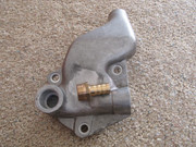
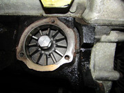
The new water pump cover together with the serious looking 12-vane water pump supplied by the Bros Rimmer offered an impressive piece of kit:
===>
Image

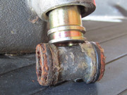
I was indeed fortunate (from what I have read) to have the old leaking 6-vane water pump jump right out of the block upon my rotating that LH thread bolt, and the new 12-vane water pump just rotated back into place with little effort on my part. Oh, my – such shiny vane surfaces:
===>
Image

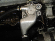
The fitting process for the new pump cover was a bit of a rigmarole. For me the biggest PITA was the measurement of the free gap between the pump cover and the block. I spent LOTS of time with feeler gauges to try and get a consistent gap measurement around the perimeter of the cover. Then it dawned on me that to this *precision* measurement, one adds anywhere between 0.0125" - 0.0250" (with no advice given on where one should aim for in this spread), so the overall accuracy required must be rather loose. I ended up using the single 0.030" gasket for the install. So new pump, cover, hoses and clamps were all finally in place:
===>
Image

Next was the high stress process of refitting the entire intake manifold assembly, as well as the bypass tube designed (probably) by a sociopath. I have already chewed all that over on a different TDC Forum thread (see page 2 there), so no need to repeat all that here. For the link there:
https://forum.triumphdolomite.co.uk/vie ... 2&start=15

Finally that intake assembly and all of its various connections and plumbing were in place. Time to do a “hydrostatic” leak test (just fill the cooling system, let it sit there quietly for several hours to see if any coolant is seeping out anywhere). And of course, it was seeping...in two spots. Fig compote! First, of course, the one and only hose that I had not replaced with a new hose was dripping at its connection to the thermostat housing. In retrospect, that hose was old and hardened, and no matter how much I tightened the hose clamp, that end of the hose would not fully seal onto the hose pipe. I had avoided replacing that hose since it looked good enough (hah!), and also its radiator end was where the Kenlowe fan temperature sensor lead was inserted, which I did not want to disturb. So I grabbed a new top left radiator hose from my stash of parts.

Of course replacing that hose disturbed the coolant temperature probe that had been residing quietly inside the hose for the past 13 years. As soon as I removed that end of the hose, the probe jumped out of the radiator pipe like a loaded spring. The Kenlowe kit has an orange silicone rubber sleeve that slides onto the radiator outlet. That sleeve has a groove along its length into which the probe lead fits so that the lead does not disturb the hose's inside diameter. The trick is keeping the lead in the groove while manhandling the end of the hose over the radiator outlet. There was a remnant of some kind of adhesive at either end of that groove, presumably used to keep the lead in the groove while the hose end is offered up, so I renewed those dabs of adhesive. I used a zip tie to hold everything in place while the adhesive solidified:
===>
Image

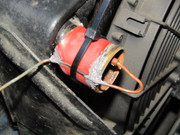
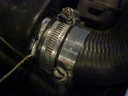
After 24 hours it was hope that the adhesive took hold and cut off the zip tie – whew, nothing moved. Then gently coax the hose end over the orange sleeve with lots of Permetex applied over the lead in the groove and at the two ends of the orange sleeve. Then to be doubly sure, I used two hose clamps, slightly offset, to provide a longer clamping surface on this end of the hose:
===>
Image

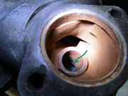
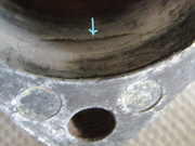
Leak tested, and both ends of the new hose remained nice and dry. But then there still was that second, very slow coolant seepage point. This one was much more concerning: the location was where the outboard bolt flange met the body of the thermostat housing. Nothing to do but partially drain the wretched cooling system once again and remove the thermostat housing to inspect its interior. After sanding off the gunk deposited on the interior surface near where the bolt flange was at the exterior of the housing, a small crack (blue arrow) showed up on the inside of the thermostat housing, double fig compote:
===>
Image

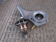
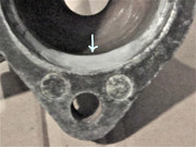
So the coolant was seeping right through the wall of the housing. I had a spare thermostat housing in hand, but it was old/used, physically totally sound, but as drab as a lump of coal. So I decided to see if I could repair my highly polished, leaking housing. I got a stick of “QuikAluminum” aluminum-reinforced epoxy putty from Polymeric Systems, which had glowing claims (I was dubious). I spread the putty over and beyond the extent of the interior crack. I also set another sample spread of putty aside on the table just to see how it cured. Within an hour, the sample had cured into a hard mass. I then waited a day and sanded down the putty that had been used for the interior crack patch for a smooth surface (at blue arrow):
===>
Image

Now on to the really serious testing. For the first time in over two months (and after significant disassembly and reassembly), PFJ was requested to crank the engine. Three twists of the key, and PFJ sprang right back to life! Then it was three times through the published procedure to feed and bleed the cooling system, each with a three minute run of the engine. Then it was out to move around the driveway under power. Then it was repeated examinations under the bonnet for any dampness anywhere for a couple of days. PFJ remained bone dry. Looks like the 12-vane water pump adventure has concluded successfully. And PFJ has joined the other Blues Brother back in the sunshine:
===>
Image

Onwards to the 17 other things I need to do to PFJ....

_________________
Current keeper of “Project PFJ”.
I was “SCMike” in a previous life on this Forum.


Top
   
PostPosted: Mon Mar 07, 2022 8:30 am 
Offline
TDC Member
User avatar

Joined: Wed Nov 15, 2017 3:35 pm
Posts: 957
Location: Filey, North Yorkshire
Nice work, and thanks for taking the time to write it up and post photos - I enjoyed reading that!

_________________
Image


Top
   
PostPosted: Tue Mar 08, 2022 2:31 pm 
Offline
Future Club member hopefully!
User avatar

Joined: Wed Dec 08, 2021 5:57 pm
Posts: 60
Location: Aiken, SC USA
Sprint Rear Brake Cylinder?

Next step: weeping right side rear brake cylinder. Before I embark upon fixing this, I thought I should check with the Brain Trust to see if there are any traps awaiting.

1. I have new GWC1121 Brake Cylinders in hand. This is for a 1974 pre-update Sprint. Is this the appropriate part, or were there any running changes in the brake cylinder design?

2. The Repair Operation Manual seems to suggest that replacing the wheel cylinder is a pretty straightforward process. Are there any tricks or complications that the Manual does not mention?

Thanks!
Mike

_________________
Current keeper of “Project PFJ”.
I was “SCMike” in a previous life on this Forum.


Top
   
Display posts from previous:  Sort by  
Post new topic  Reply to topic  [ 69 posts ]  Go to page Previous 1 2 3 4 5 Next

All times are UTC+01:00


Who is online

Users browsing this forum: No registered users and 45 guests


You cannot post new topics in this forum
You cannot reply to topics in this forum
You cannot edit your posts in this forum
You cannot delete your posts in this forum
You cannot post attachments in this forum

Search for:
Jump to:  
Powered by phpBB® Forum Software © phpBB Limited