The Triumph Dolomite Club - Discussion Forum

The Number One Club for owners of Triumph's range of small saloons from the 1960s and 1970s.
It is currently Thu Apr 18, 2024 7:18 am

All times are UTC+01:00


Post new topic  Reply to topic  [ 102 posts ]  Go to page 1 2 3 4 57 Next
Author Message
 Post subject: Start of new project.
PostPosted: Tue Nov 29, 2011 10:30 pm 
Offline
Future Club member hopefully!
User avatar

Joined: Thu Oct 06, 2011 1:13 am
Posts: 3173
Location: The continent
Just started tonight on my new engine. My current daily driver isn't that good anymore so a new engine.
I could take the current engine apart but then i have to go by bus to my work and that's no option. And when there's a lot of snow outside soon it would be very frustrating not to have a running rwd dolomite on the parkingspace.

The one i'm going to use is an engine that i drove in another car for about 10.000 miles and was totally std, so std cams and hs6's. Only optimized and had about 135hp on the rearwheels and a crazy compression ratio of 1:11,5. It could only run on octane 98 or higher. The first thing i did tonight was change the camshaft for a st rally gp2 cam, just to see if it was possible and the valves did not tough the pistons. This was all ok. The next thing is to take it apart for a check. This engine is becoming fuel injection on a weber manifold. I'm not going to use weber type throttlebodies but want to fit the injectors in the manifold, just in front of the inlet valves. Will keep you informed.

It was not that warm in the shed but this way i have the same working conditions as the ST guy's at Abingdon at the time and have the same tolerances measured. :mrgreen:
Attachment:
camshaft.JPG
camshaft.JPG [ 468.48 KiB | Viewed 8148 times ]

_________________
Classic Kabelboom Company. For all your wiring needs. http://www.classickabelboomcompany.com


Top
   
PostPosted: Tue Nov 29, 2011 11:02 pm 
Offline
Future Club member hopefully!
User avatar

Joined: Wed Jan 23, 2008 5:19 am
Posts: 3210
Location: Old Basing, Hants.
Very very interested in how your manifold turns out, I had similar thoughts circling in my head.
Though unlike yourself, I lack err, pretty much everything to make it a reality. :lol:
"Know ones limits master Wayne." etc.

_________________
1978 Sandglow Dolomite 1850HL The Lolomite - MOT pass! (broken again in 55 miles though...)
It's 106 miles to Chicago, we've got a full tank of gas, half a pack of cigarettes, it's dark, and we're wearing sunglasses.
Hit it.
Image


Top
   
PostPosted: Mon Dec 05, 2011 10:44 pm 
Offline
Future Club member hopefully!
User avatar

Joined: Thu Oct 06, 2011 1:13 am
Posts: 3173
Location: The continent
Little update:

Time for some pipe bending. I have determined the location of the plenum, a tr7 one. This set up should fit into the bay and have space enough to fit the injection rail between the plenum and manifold. To the end of this week i will cut some flanges where the pipes are going to be weld on.
Attachment:
fuel1.JPG
fuel1.JPG [ 435.92 KiB | Viewed 7961 times ]
Attachment:
fuel2.JPG
fuel2.JPG [ 423.65 KiB | Viewed 7959 times ]
Attachment:
fuel3.JPG
fuel3.JPG [ 456.98 KiB | Viewed 7958 times ]

_________________
Classic Kabelboom Company. For all your wiring needs. http://www.classickabelboomcompany.com


Top
   
PostPosted: Tue Dec 06, 2011 4:18 am 
Here is how my EFI set up is done. I originally made it back in the late 1990's and would probably do it different if I was doing it again, but it still works fine.

[img]
Attachment:
EFIquad.jpg
EFIquad.jpg [ 266.7 KiB | Viewed 7913 times ]
[/img]

And here is a twin throttle body set up

[img]
Attachment:
EFIquad.jpg
EFIquad.jpg [ 266.7 KiB | Viewed 7913 times ]
[/img]

good luck with the build.

Mark


Attachments:
EFI (1).JPG
EFI (1).JPG [ 296.72 KiB | Viewed 7920 times ]
Top
   
PostPosted: Thu Dec 08, 2011 1:44 am 
Have done that 15 years ago with good results. car is still running fine, very good fuel economy to.
Used Weber 40mm throttle body's, pump and sensors, DTA programmable management and missing tooth wheel direct behind the front pulley.
Took the distributor of and used only the bearing part to support the oil pump sprocket, 4 pole dis ignition.

6 Sept 1997 (Diana's Funeral) we went to Sodid somewhere north of London and had a technical price for it, and the long distance award.

Only some old pictures digi was not that wide spread those days.

Hans

Image

Image

Image


Top
   
PostPosted: Thu Dec 08, 2011 11:51 am 
Offline
Future Club member hopefully!
User avatar

Joined: Thu Oct 06, 2011 1:13 am
Posts: 3173
Location: The continent
I would like to have one throttlevalve that's why i did choose this setup. Also the injectors in the manifold, as close as possible to the inletvalves.

I'm going to weld the bulges of a jag xj6 on the manifold. These can accept the Bosch L jetronic injectors that are in the jag and tr7.

The flanges are on the inletmanifold/plenum. The extensions are going to be bend 90 degrees. Two on the upper side to fit the fuel rail to and two on the lower side to have the wiring loom attached to.

Jeroen
Attachment:
adapter.JPG
adapter.JPG [ 235.49 KiB | Viewed 7702 times ]
Attachment:
flange.JPG
flange.JPG [ 187.68 KiB | Viewed 7690 times ]

_________________
Classic Kabelboom Company. For all your wiring needs. http://www.classickabelboomcompany.com


Top
   
PostPosted: Tue Dec 13, 2011 10:52 pm 
Offline
Future Club member hopefully!
User avatar

Joined: Thu Oct 06, 2011 1:13 am
Posts: 3173
Location: The continent
Little update:

I have about 2 hours a week time to spend on this one so a little progress.
The flanges are attached and the tubes welded on. They are 30 degrees bend and the first one 45. This to have all the curves the same just for the looks because this one does turn back a little also. I could have moved the plenum a bit forwards to have 4 identical pipes but the plenum has to be on this exact position. This engine replaces my LPG fuel injected 1850 that has run about 260.000km now and is the last 2 months on 3 cylinders. The Impreza sound.

Having it this way i do not have to modify the airflowmetre tube and the wiring loom can also stay the same.

Jeroen
Attachment:
plenum1.JPG
plenum1.JPG [ 344.59 KiB | Viewed 7496 times ]
Attachment:
plenum2.JPG
plenum2.JPG [ 312.35 KiB | Viewed 7484 times ]
And this is in a few weeks the most famous chain tensioner. it will be know the rest of it's life as THE HYDROLIC TENSIONER. :woohoo:
Attachment:
hydrolic tensioner!!!.JPG
hydrolic tensioner!!!.JPG [ 325.07 KiB | Viewed 7453 times ]

_________________
Classic Kabelboom Company. For all your wiring needs. http://www.classickabelboomcompany.com


Top
   
PostPosted: Mon Jan 30, 2012 10:16 pm 
Offline
Future Club member hopefully!
User avatar

Joined: Thu Oct 06, 2011 1:13 am
Posts: 3173
Location: The continent
Some updates with bad pictures:

The plan has changed a bit. The plenum is ready and has now the petrol injectors in it. The first idea was to have the injectors on the inlet manifold but there's not enough space for petrol and LPG injectors so the petrol's had to move to the plenum. Not the most ideal but it's just for starting or driving with an empty LPG tank. For the clean look i have fitted the injectors and the fuel rail under the plenum so the tubes stay visible and not much hosing over the engine. The engine block is very clean now and is being skimmed about 0,3mm for even more compression. This engine block is already modified, the cooling and oilchannels but will post pictures later. A genuine Ford hardened oilpump driveshaft is also in da house.

The head is matched with the inlet manifold and doweled to have it alway's on the right spot. The seats are modified for LPG and the inlet ports widened. The only thing to do is the head doweling to the engine block when everything comes back from the machineshop.

The engine mountings are now going to have their most ultimate modification. A few years now i have my subframes modified to two angeled mountings so the oilpump cannot tough the steering rack. 1850 wise but then with a sprint subframe and mountings. The thing to do tomorrow is to fabricate whole new brackets with round rubbers in it, like the gp2 sprints and almost all gp4 escorts. This way the engine cannot move or rotate as much.

The pictures are from the old 1850 engine with a temporary sprint head just to try and decide the height of the engine. The engine was very high in the car because of sump protection but with a sprint head it has to be lowered again.

Jeroen
Attachment:
plenum1.JPG
plenum1.JPG [ 42.09 KiB | Viewed 6974 times ]
Attachment:
plenum2.JPG
plenum2.JPG [ 40.49 KiB | Viewed 6939 times ]
Attachment:
plenum3.JPG
plenum3.JPG [ 38.87 KiB | Viewed 6923 times ]

_________________
Classic Kabelboom Company. For all your wiring needs. http://www.classickabelboomcompany.com


Top
   
PostPosted: Mon Jan 30, 2012 10:17 pm 
Offline
Future Club member hopefully!
User avatar

Joined: Thu Oct 06, 2011 1:13 am
Posts: 3173
Location: The continent
.
Attachment:
plenum4.JPG
plenum4.JPG [ 40.27 KiB | Viewed 6897 times ]
Attachment:
plenum5.JPG
plenum5.JPG [ 54.38 KiB | Viewed 6887 times ]
Attachment:
plenum6.JPG
plenum6.JPG [ 51.68 KiB | Viewed 6884 times ]

_________________
Classic Kabelboom Company. For all your wiring needs. http://www.classickabelboomcompany.com


Top
   
PostPosted: Mon Jan 30, 2012 10:54 pm 
Oh lordy lordy, my poor dyno. :mrgreen:
Still knowing what his old 1850on LPG did put out, this will pretty much more I expect.

BDW I wouldn't be surprised that with all this compression the engine will even take a 3' fuel, DIESEL :lol: :lol: :lol:

Hans


Top
   
PostPosted: Mon Jan 30, 2012 11:43 pm 
Offline
Future Club member hopefully!
User avatar

Joined: Fri Nov 23, 2007 11:33 pm
Posts: 4727
Location: hampshire
Good stuff our Netherland friends. :bluewave:

_________________
track action maniac.

The lunatic is out................heres Jonny!


Top
   
PostPosted: Tue Feb 14, 2012 7:23 pm 
Offline
Future Club member hopefully!
User avatar

Joined: Thu Oct 06, 2011 1:13 am
Posts: 3173
Location: The continent
Hello, little update:

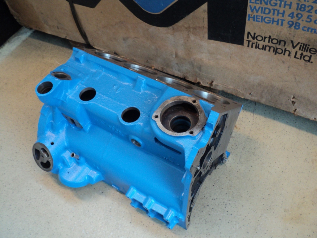
The engineblock is almost ready. Only the head dowels must go in and that will be Saturday.

At first the deck is skimmed 0,3mm and the compression ratio will be now 1:12. The deck is skimmed on a special device that is connected on the main bearing part of the block. Dolomite engines are never drilled straight and this way the deck is flush with the crankshaft bore. The piston are now evenly above the deck. Before there was a difference from about 0,15mm. The first was straight with the deck and the fourth was 0,15 below. It can also be seen on the jackshaft keep plates. There's alway's wear on 60% of the half circle so the jackshafts are not 90 degrees in line but alway's a bit off.

I did want a better oilflow to the camshaft and decided to have an extra external oilpipe to the head on the rear of the engine and head. The rear jackshaft bearing would be my take off. The oilflow at the front is pulsating to the head. This is to maintain good lubrication for the bottom end. I'm going to make a little flat spot on the rear jackshaft journal, exactly timed with the front so at the same time oil is pushed from two way's to the camshaft and rocker shaft. This is why the external oilfeed kits are bugger because the direct oilflow goes to the rockershaft giving too much oil what's intended for the bottom end. The pulsating on the ohc 4 and 6 cyl is by a flat spot on the rear of the camshaft.
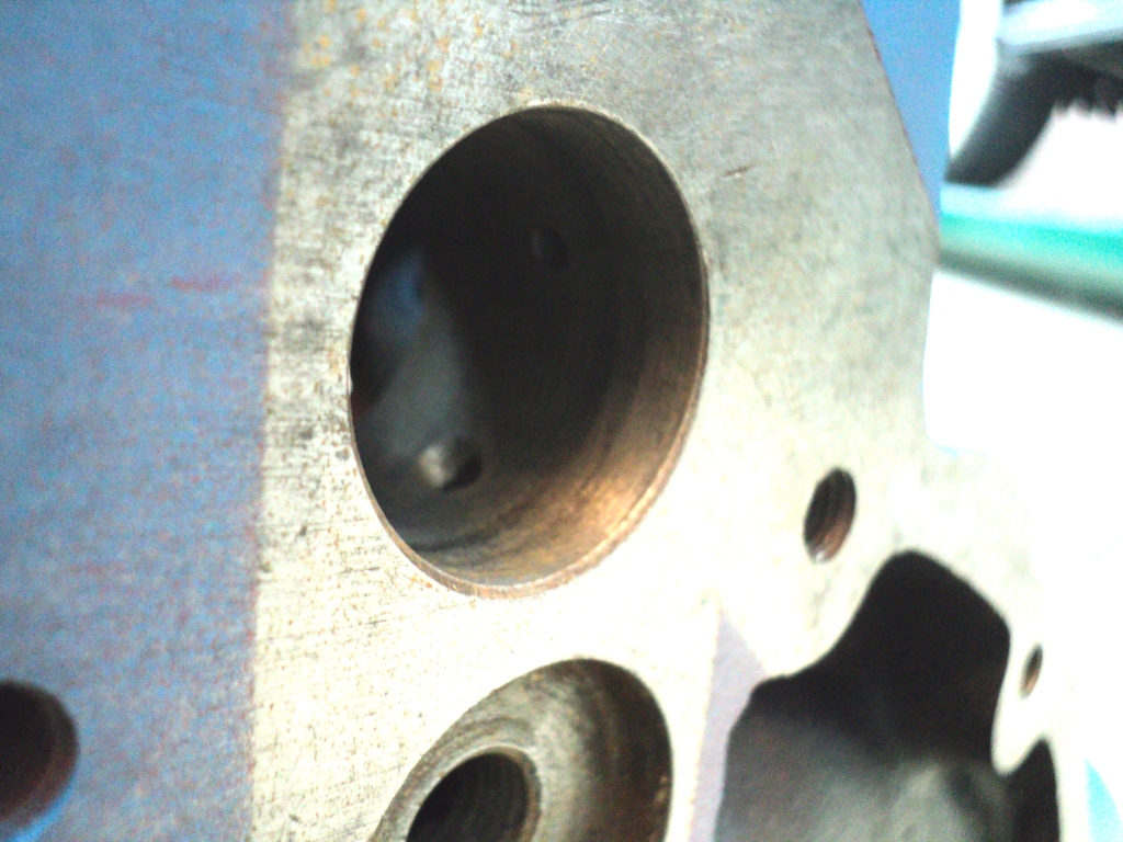
When measuring the exact hole for the take of i discovered that the main feed is not lined up with the groove in the jackshaft. The overlap was 0,8mm. The oilbore is about 4,5mm and the groove is 4,75mm. You can see the darker part where the groove is. I did make the main oilhole a bit oval towards the groove to have more oil there for total lubrication of that journal and for the distributor/oilpump gear what also gets here the oil from.

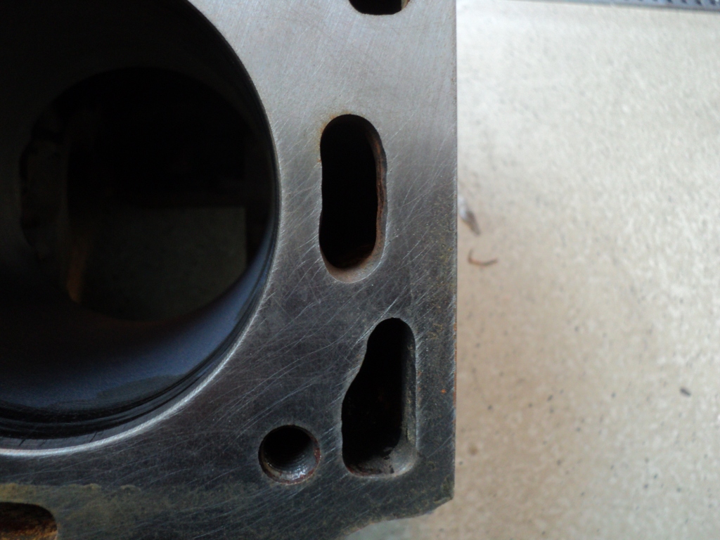
I opened up the waterway's to match my base head gasket. This gasket is also on the head and so the waterway's are matched.
Attachment:
engine0.JPG
engine0.JPG [ 328.27 KiB | Viewed 6534 times ]
Attachment:
engine1.JPG
engine1.JPG [ 355.92 KiB | Viewed 6595 times ]
Attachment:
engine3.JPG
engine3.JPG [ 305.75 KiB | Viewed 6518 times ]

_________________
Classic Kabelboom Company. For all your wiring needs. http://www.classickabelboomcompany.com


Top
   
PostPosted: Tue Feb 14, 2012 7:32 pm 
Offline
Future Club member hopefully!
User avatar

Joined: Thu Oct 06, 2011 1:13 am
Posts: 3173
Location: The continent
I also opened up the oilway's. In the filter area the holes are very small and can be bigger. The pick up is enlarged and matched with the pick up pipe. There are two threaded holes in the filter housing and that is to have the spin on adapter attached. The normal kit has a "floating" adapter part and when changing a modern filter the adapter turns a bit and loosens and then you still have to replace the rubber ring that's in the block and that is not what you want with your spin on conversion. Two allen bolts now tighten the adapter part so it does not turn or loosens when a filter is changed. The oilfilter/block are matched and opened up. There's also an extra hole for the oilpressure gauge sender. That was with a t piece on the oilcooler take off plate but the oilpipes were a bit akward because of this so the place for the sender.
Attachment:
engine7.JPG
engine7.JPG [ 344.24 KiB | Viewed 6514 times ]
Attachment:
engine8.JPG
engine8.JPG [ 294.1 KiB | Viewed 6630 times ]
Attachment:
engine9.JPG
engine9.JPG [ 341.07 KiB | Viewed 6500 times ]

_________________
Classic Kabelboom Company. For all your wiring needs. http://www.classickabelboomcompany.com


Top
   
PostPosted: Tue Feb 14, 2012 7:43 pm 
Offline
Future Club member hopefully!
User avatar

Joined: Thu Oct 06, 2011 1:13 am
Posts: 3173
Location: The continent
Attachment:
engine6.JPG
engine6.JPG [ 349.67 KiB | Viewed 6471 times ]
The most importand mod was to have the bore angles rounded. Most of the blocks are bored too deep and the cylinderbore goes into the treaded hole of the main bearing cap bolts. If you have one like this with no touched holes it's a good base for reliable power. This was a 1850 and there's even more flesh left and rebored less deep to 2000cc. To have these parts rounded there's less change they tear and break. There are a lot of blocks with little cracks straight through the bolt holes. Lazy sprints and 1850 will never notice this but at serious revs and power the block cracks and the mainbearingcaps come loose. You can fit an engine brace but the ones sold with the larger studs and extra nuts do no job. It still can bend a bit and a block can crack. The only thing they do is when they crack the cranckshaft will not fall into the sump immediately. When rounding these sharp edges the change is minim. I did sandblast the rounded edges to have all the fine scratches removed also.
Attachment:
engine4.JPG
engine4.JPG [ 302.46 KiB | Viewed 6470 times ]
Attachment:
engine5.JPG
engine5.JPG [ 384.99 KiB | Viewed 6472 times ]

_________________
Classic Kabelboom Company. For all your wiring needs. http://www.classickabelboomcompany.com


Top
   
PostPosted: Wed Feb 15, 2012 7:59 pm 
Offline
TDC Member
User avatar

Joined: Fri Oct 20, 2006 10:10 am
Posts: 380
Location: Netherlands
Ha Jeroen, very impressive! I'm jealous:-)

Now the block is save, how many revs are you planning to use? And with the big compression, you need a cam with a big overlap. Does the LPG cope with that, so minimum chanches on back-fire?

I'm curious to the power output, I'm sure you'll beat your previous record;-)

Groeten,

_________________
Ronald
Club Triumph Holland - Dolomite Registrar


www.triumphowners.com/tahitisprint


Top
   
Display posts from previous:  Sort by  
Post new topic  Reply to topic  [ 102 posts ]  Go to page 1 2 3 4 57 Next

All times are UTC+01:00


Who is online

Users browsing this forum: No registered users and 10 guests


You cannot post new topics in this forum
You cannot reply to topics in this forum
You cannot edit your posts in this forum
You cannot delete your posts in this forum
You cannot post attachments in this forum

Search for:
Jump to:  
Powered by phpBB® Forum Software © phpBB Limited