DTR - Project Recommission 1972 'Dolomite' Manual
-
yorkshire_spam

- Guest contributor

- Posts: 990
- Joined: Wed Nov 15, 2017 3:35 pm
- Location: Filey, North Yorkshire
Re: DTR - Project Recommission 1972 'Dolomite' Manual
Binny's plates are fab.... get some like hers!

Re: DTR - Project Recommission 1972 'Dolomite' Manual
I got them from Tippers Sam, they are nice!
I'll order some!
Brakes are bled, need to sit and I'll bleed them again, pedal's spongy, pretty normal after an empty fill.
All I need now is an engine!!
I'll order some!
Brakes are bled, need to sit and I'll bleed them again, pedal's spongy, pretty normal after an empty fill.
All I need now is an engine!!
-
Richard the old one
- TDC Member
- Posts: 1217
- Joined: Thu Sep 28, 2006 10:06 pm
- Location: Bristol
Re: DTR - Project Recommission 1972 'Dolomite' Manual
Hi James.
I am sorry and did not know if I should raise this but I have just been looking through your progress reports and am concerned to read that the layshaft needle bearings are 0.4mm larger than the original as way back it was stated that people were having problems because a metric equivalent was being supplied that was larger than the imperial and that this caused problems when they warmed up and expanded. This must have been in the late 1980's at a guess.
I wonder if there is any other old timers in the club that could shed some light on this or just confirm that the ones you have used will be O.K
What we need is the original size and tolerance allowance for the needle rollers.
I also believe at about the same time there was a batch of layshafts which were not case hardened correctly so this might have been part of the problem.
-
MIG Wielder
- TDC Member
- Posts: 2336
- Joined: Sun Mar 16, 2008 2:52 pm
Re: DTR - Project Recommission 1972 'Dolomite' Manual
Hi James / Richard, Yes I remember reading of this problem from our Jon, and he was told to leave one needle roller out so the rest fitted. And it all went pear shaped.
Now I have my new 1850 layshaft here with the new needle rollers which I got from Rimmers and they look good.
I promised James the measurements, so here they are. ( Hope my maths is O.K. )
Diameter of layshaft = 16.630mm
Needle roller dia = 2.355mm ( check on 4 samples.)
So circumference of layshaft = Pi x 16.630 = 52.2446 mm.
Rolling diameter of the needle rollers = 18.9850 mm ( diameter of shaft + 2 needle roller radii )
Therefore rolling circumference of needle rollers = Pi x 18.950 = 59.643 mm.
Therefore number of needle rollers required = 59.643/ 2.355 = 25.326 rollers.
So you can fit 25 complete rollers ( correct number) and have a total gap of 0.326 of the diameter of a roller.
Which = 0.326 x 2.355mm = 0.7677mm between 25 rollers or 0.0307 mm between each roller when fitted.
Or about 1.2 thou;
I think this is reasonable ?
I reckon I'm very happy to use these as well.
Tony.
Edited: 3/5/18 to correct the maths. Thanks Richard !
Last edited by MIG Wielder on Thu May 03, 2018 5:53 pm, edited 1 time in total.
-
Richard the old one
- TDC Member
- Posts: 1217
- Joined: Thu Sep 28, 2006 10:06 pm
- Location: Bristol
Re: DTR - Project Recommission 1972 'Dolomite' Manual
Hi
This is testing my maths etc
I can see how the rolling circumference is 59.6431mm
so if the diameter of each roller is 2.355 we could fit 59.6431/2.355 = 25.326 rollers
so the total gap is 0.326 X diameter of a roller 0.326 X 2.355 which I work out to be 0.7677 not the 0.8256 shown above
Hence the gap between rollers is 0.7677 / 25 = 0.0307mm against 0.033mm which comes out as just 1.2thou
NOT MUCH but I do not know what to expect and we have not considered any expansion that will take place when the gearbox warms up.
It would be interesting to measure some original rollers and an original layshaft diameter.
Do we have the means to measure the internal diameter of the laygear bearing surface so that we could work out the clearance between rollers and bearing surface.
It has been a hard day so please people check my maths first and give your thoughts
-
MIG Wielder
- TDC Member
- Posts: 2336
- Joined: Sun Mar 16, 2008 2:52 pm
Re: DTR - Project Recommission 1972 'Dolomite' Manual
Hi Richard, Thanks for the corrections. I don't know how I got that wrong. I do have a spare lay-shaft here; if I can get the bearing rings out I'll try and measure them.
Cheers for now,
Tony.
Cheers for now,
Tony.
-
Richard the old one
- TDC Member
- Posts: 1217
- Joined: Thu Sep 28, 2006 10:06 pm
- Location: Bristol
Re: DTR - Project Recommission 1972 'Dolomite' Manual
I have measured some needle rollers and a couple of layshafts to see how they compared with your findings. The details are below
The needle rollers that I measured were very slightly bigger and as a result the figures work out as follows.
Diameter of layshaft = 16.630mm 0.655in
Needle roller dia = 2.362mm ( check on 4 samples.) 0.093th / 0.03937
Against MIG Wielder’s 2.355mm so very little 0.007mm bigger
Rolling diameter of the needle rollers = 18.992 mm ( diameter of shaft + 2 needle roller radii ) Against 18.9850
Therefore rolling circumference of needle rollers = Pi x18.992 =59.665 mm. Against 59.643
Therefore number of needle rollers required = 59.665 / 2.362 = 25.26 rollers. Against 25.326
So you can fit 25 complete rollers ( correct number) and have a total gap of 0.26 of the diameter of a roller. Against 0.326
Which = 0.26 x 2.362mm = 0.61412 mm between 25 rollers
Against 0.8256
or 0.02456mm Against 0.033 between each roller when fitted.
Or about 0.9 thou; Against 1.3 thou
Please check my figures.
But as the needle rollers are bigger this would leave less room in general
I purchased the needle rollers a long time ago, it could have been in the 1980’s
I ALSO BELIEVE THAT THERE WAS A BATCH OF LAYSHAFTS THAT HAD NOT BEEN CORRECTLY CASE HARDENED WHICH COULD HAVE BEEN THE MAIN CAUSE OF PROBLEMS IN THE PAST.
Last night I attended the Bristol Triumph owners monthly meeting and got them to check my measurements as it is a long time ago that I used a micrometer and I asked their views on the amount of clearance that they would expect. They thought it would be very small.
If nothing else we have at least come up with some guidance on the size of rollers.
Re: DTR - Project Recommission 1972 'Dolomite' Manual
I have spoken to a few suppliers and they have said that they haven't seen a problem with layshafts or needle rollers, one local specialist told me that this was an issue in the 80's and early '90s. He also said that every single rail or three rail gearbox has probably been rebuilt at least once in its lifetime and that needle rollers will wear which is why they are replaced and most problems were caused by the wrong oil being used and gearboxes being run dry.
Given the application of these gearboxes, MG's, Spitfires, Dollys, GT6's, Marinas etc... and how many rebuild kits are sold I am not in any way concerned about the quality of the parts that have been supplied.
Given the application of these gearboxes, MG's, Spitfires, Dollys, GT6's, Marinas etc... and how many rebuild kits are sold I am not in any way concerned about the quality of the parts that have been supplied.
Re: DTR - Project Recommission 1972 'Dolomite' Manual
I am hoping that the engine should be ready for me today.
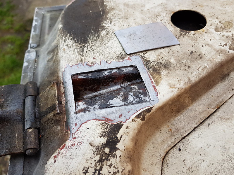
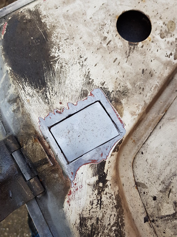
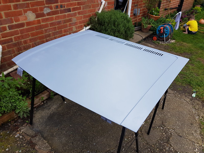
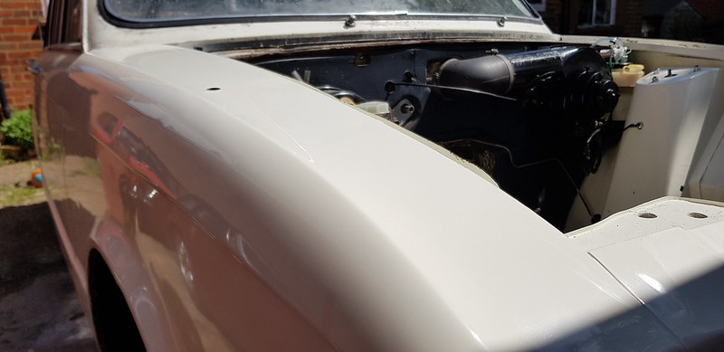
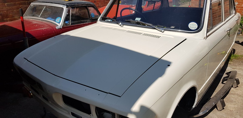
I found some rust on the bonnet hinge mount and had to do a repair
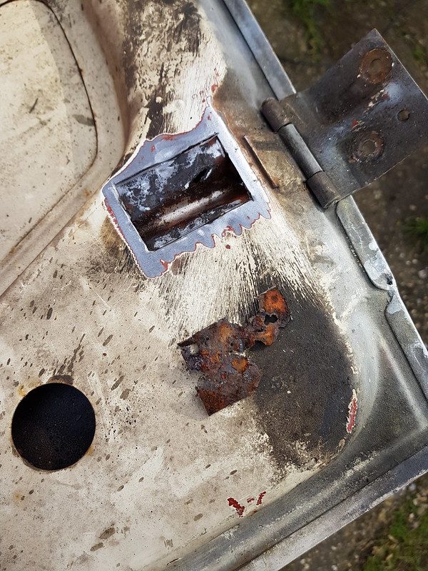
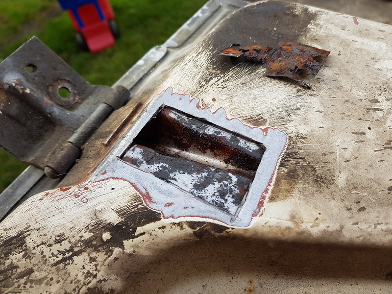
It has had some rust killer in there and a bit of wax
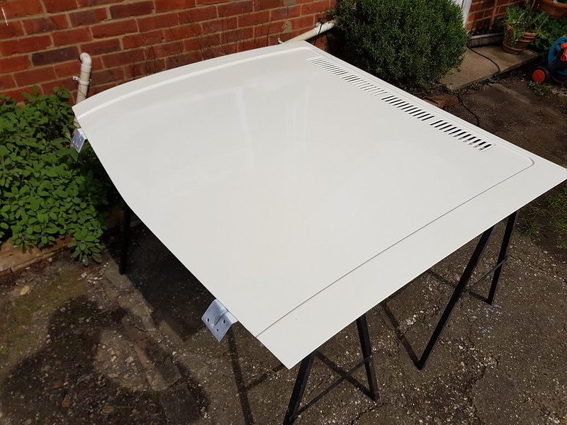
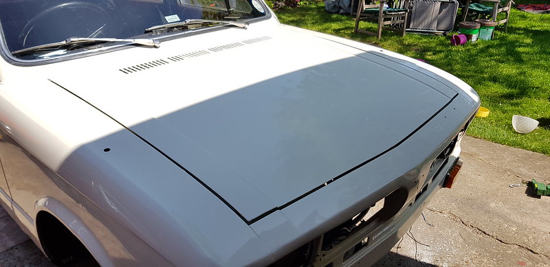
I want to spray the underside of the bonnet and ran out of paint so I'll do that this weekend. I did get to spray the top of the bonnet though
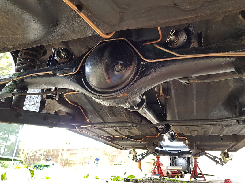
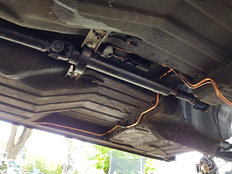
Fitted the prop ready for the engine and gearbox to go back in.
New mirrors arrived today!
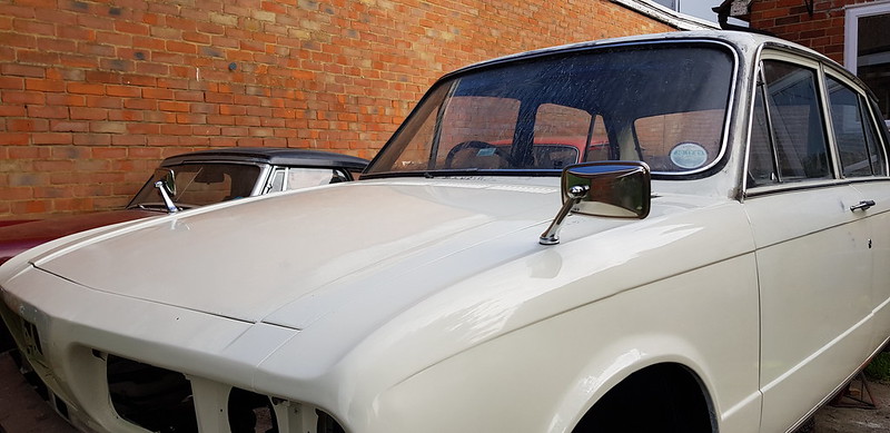
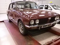
Test fitted everything, I need to make a couple of adjustments but it's all fine. It actually looks like a car again!!!
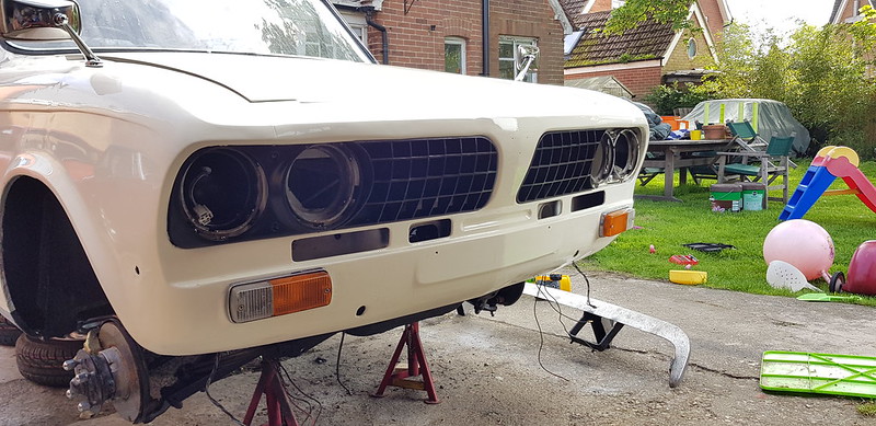
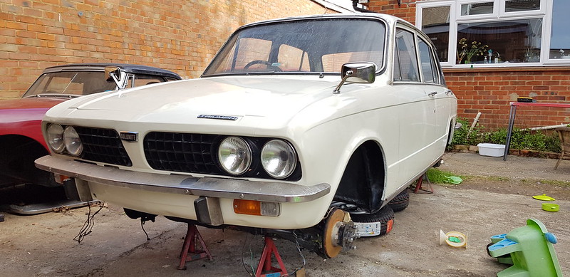
Just need to paint the headlamp surrounds and finish the wiring, plates should arrive tomorrow.
If I have an engine I should be on the road by next weekend.
I found some rust on the bonnet hinge mount and had to do a repair
It has had some rust killer in there and a bit of wax
I want to spray the underside of the bonnet and ran out of paint so I'll do that this weekend. I did get to spray the top of the bonnet though
Fitted the prop ready for the engine and gearbox to go back in.
New mirrors arrived today!
Test fitted everything, I need to make a couple of adjustments but it's all fine. It actually looks like a car again!!!
Just need to paint the headlamp surrounds and finish the wiring, plates should arrive tomorrow.
If I have an engine I should be on the road by next weekend.
-
Richard the old one
- TDC Member
- Posts: 1217
- Joined: Thu Sep 28, 2006 10:06 pm
- Location: Bristol
Re: DTR - Project Recommission 1972 'Dolomite' Manual
Hi James.
You have obviously got to the bottom of the gearbox problem and as you state we should not have a problem with current spares.
I was glad to read that one local specialist confirmed that there was an issue in the 80's and early 90's. He must have been another old boy like myself who was around at the time.
Re: DTR - Project Recommission 1972 'Dolomite' Manual
Sorry, Richard I wasn't ignoring your initial posts, I just realised the amount of time it took me to reply!
Engine update, should be ready tomorrow!
Standard mains and plus 10 on the big ends, the crank looks so good! Small ends replaced, flywheel has been faced, everything balanced.
Block has been bored and faced.
Head is fine, looks to be a replacement at some point, will face it and check the valve stems.
-
MIG Wielder
- TDC Member
- Posts: 2336
- Joined: Sun Mar 16, 2008 2:52 pm
Re: DTR - Project Recommission 1972 'Dolomite' Manual
Hi James / Richard, Interesting that Richard has very similar measurements to my own.Richard the old one wrote: ↑Wed May 02, 2018 8:11 pm Hi
Do we have the means to measure the internal diameter of the laygear bearing surface so that we could work out the clearance between rollers and bearing surface.
I found the old 1850 layshaft and extracted a needle roller retaining ring.
With a micrometer I reckon the overage O.D. of this is 21.44 mm. Now this is a tight fit in the layshaft bore.I have a pair of callipers and I checked the bore in the unworn section. This averaged out at 21.41 mm.
So I reckon the running clearance is Layshaft dia + 2 x needle roller dia = 21.340 mm
So the running clearance is 0.070 mm, or 1/2 of this radially = 0.035 mm ( or about 1.4 thou radially.
Does this sound O.K. please ? The only figure I have is 4 - 6 thou running clearance on front wheel bearings.
Tony.
Re: DTR - Project Recommission 1972 'Dolomite' Manual
I may have missed a bit, but wouldnt the clearance diameter be based on 2 rollers being exactly opposite to get an acurate reading?.MIG Wielder wrote: ↑Fri May 04, 2018 6:01 pmHi James / Richard, Interesting that Richard has very similar measurements to my own.Richard the old one wrote: ↑Wed May 02, 2018 8:11 pm Hi
Do we have the means to measure the internal diameter of the laygear bearing surface so that we could work out the clearance between rollers and bearing surface.
I found the old 1850 layshaft and extracted a needle roller retaining ring.
With a micrometer I reckon the overage O.D. of this is 21.44 mm. Now this is a tight fit in the layshaft bore.I have a pair of callipers and I checked the bore in the unworn section. This averaged out at 21.41 mm.
So I reckon the running clearance is Layshaft dia + 2 x needle roller dia = 21.340 mm
So the running clearance is 0.070 mm, or 1/2 of this radially = 0.035 mm ( or about 1.4 thou radially.
Does this sound O.K. please ? The only figure I have is 4 - 6 thou running clearance on front wheel bearings.
Tony.
Tony
Membership 2014047
-
Carledo
- TDC Shropshire Area Organiser
- Posts: 7242
- Joined: Sun Aug 21, 2011 5:12 pm
- Location: Highley, Shropshire
Re: DTR - Project Recommission 1972 'Dolomite' Manual
Since the general consensus (and Triumph themselves) reckon there are 25 needle rollers at each end, there are NEVER 2 rollers diametrically opposite each other! But with 25 rollers, I doubt the difference will matter!tony g wrote: ↑Fri May 04, 2018 8:44 pmI may have missed a bit, but wouldn't the clearance diameter be based on 2 rollers being exactly opposite to get an acurate reading?.MIG Wielder wrote: ↑Fri May 04, 2018 6:01 pmHi James / Richard, Interesting that Richard has very similar measurements to my own.Richard the old one wrote: ↑Wed May 02, 2018 8:11 pm Hi
Do we have the means to measure the internal diameter of the laygear bearing surface so that we could work out the clearance between rollers and bearing surface.
I found the old 1850 layshaft and extracted a needle roller retaining ring.
With a micrometer I reckon the overage O.D. of this is 21.44 mm. Now this is a tight fit in the layshaft bore.I have a pair of callipers and I checked the bore in the unworn section. This averaged out at 21.41 mm.
So I reckon the running clearance is Layshaft dia + 2 x needle roller dia = 21.340 mm
So the running clearance is 0.070 mm, or 1/2 of this radially = 0.035 mm ( or about 1.4 thou radially.
Does this sound O.K. please ? The only figure I have is 4 - 6 thou running clearance on front wheel bearings.
Tony.
Tony
Back in the 80s I built a LOT of 3 rail boxes for GT6 and Vitesse and a couple failed early from too high a cheese content in the layshaft! After inspecting a few, both good and bad, I came to the conclusion that you could tell a duff one from the colour and shine on it, A good one was brighter and lighter than a bad one. After that I rejected a few from the suppliers and then the duff ones stopped turning up. But I never had another early failure!
Steve
'73 2 door Toledo with Vauxhall Carlton 2.0 8v engine (The Carledo)
'78 Sprint Auto with Vauxhall Omega 2.2 16v engine (The Dolomega)
'72 Triumph 1500FWD in Slate Grey, Now with RWD and Carledo powertrain!
Maverick Triumph, Servicing, Repairs, Electrical, Recomissioning, MOT prep, Trackerjack brake fitting service.
Apprentice served Triumph Specialist for 50 years. PM for more info or quotes.
Re: DTR - Project Recommission 1972 'Dolomite' Manual
Great, so the gearbox situation is sorted!
Time for the final fit.
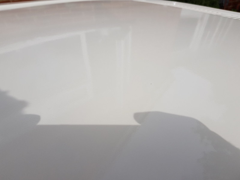
Final polish and fitted the badge pin inserts
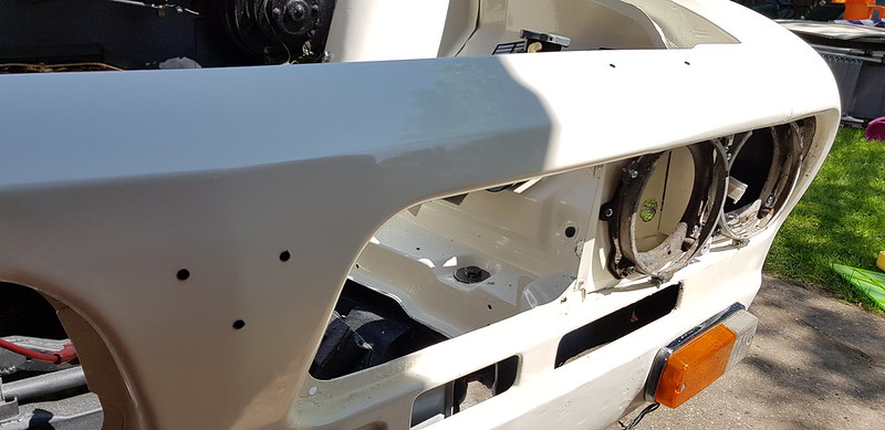
I found an existing mounting hole in the inner wing and made a bracket to hold the relays for the headlights.
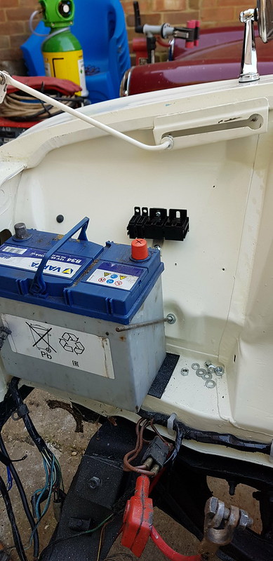
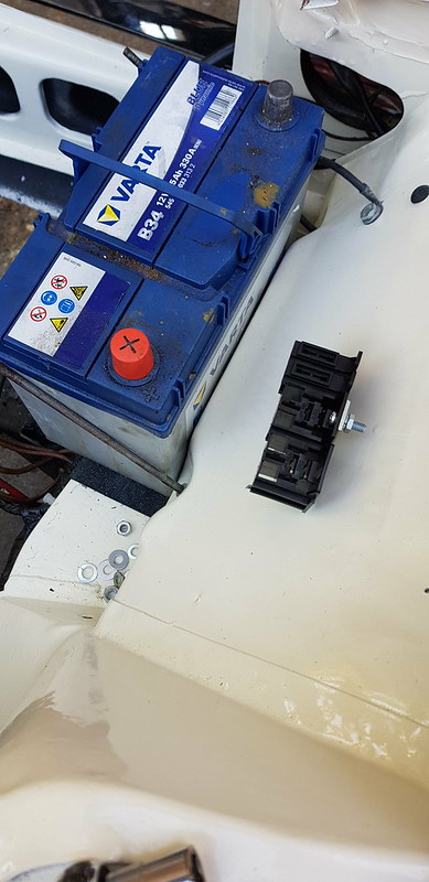
Some fresh wires to the headlights and loom tape later...
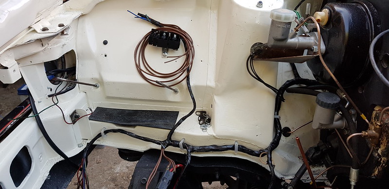
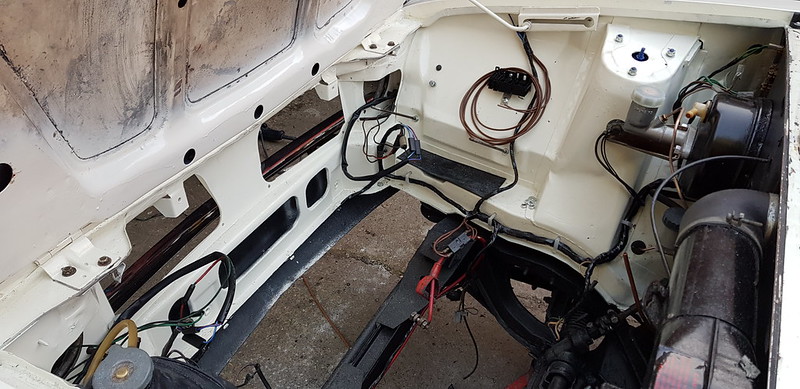
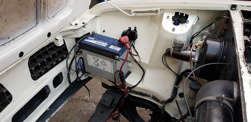

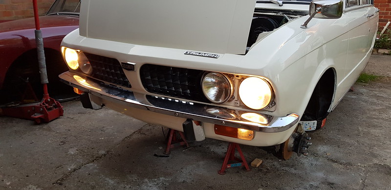
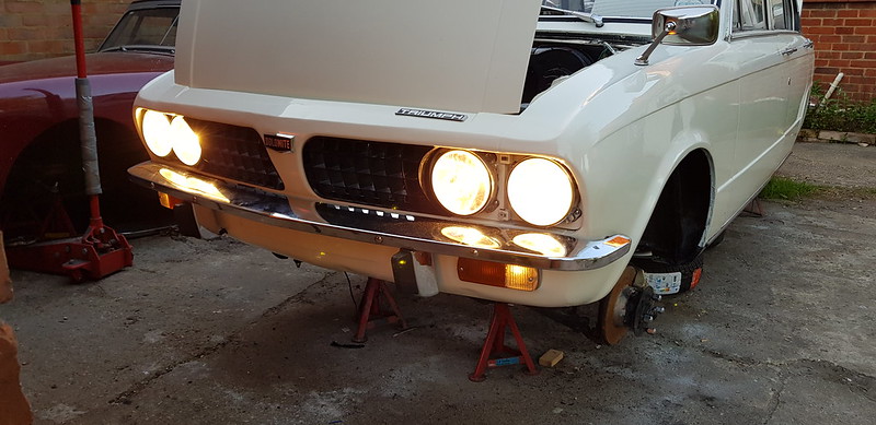
and we have headlights!
I don't have main beam flash on the stalk but that could just be a contact so I'll look at that tomorrow when I tidy up the wiring and check the rest of the electrical system.
I will spray the inside of the bonnet, it's just temporary! Well, it has to come off again for the engine to go in anyway!
Time for the final fit.
Final polish and fitted the badge pin inserts
I found an existing mounting hole in the inner wing and made a bracket to hold the relays for the headlights.
Some fresh wires to the headlights and loom tape later...
and we have headlights!
I don't have main beam flash on the stalk but that could just be a contact so I'll look at that tomorrow when I tidy up the wiring and check the rest of the electrical system.
I will spray the inside of the bonnet, it's just temporary! Well, it has to come off again for the engine to go in anyway!