So, as I wire up a new stereo, I thought it is as good a time as any to upgrade.
I have searched the Forum for some old threads to help but cannot come up with anything resembling a 'How To' guide.
Problem is, I'm an idiot in such matters so am reliant upon everyone's help in this area.
So, if anyone can contribute to creating a kind of 'How To' guide, I would be most grateful, and hopefully it will be useful for plenty of others too...(something I often wish we had more of on this Forum as I know so many of us ask the same questions over and over again).
Aims of the upgrade -
1. Split circuits across more fuses to reduce the chances of mass failure
2. Split circuits across more fuses to help fault diagnosis when a problem does occur
3. Fit a suitable fuse box that can fit in place of the existing box
4. Have space for spare fuses to enable any new circuits (like for the stereo) to be fused independently to keep subsequent wiring simple
5. Use reasonably priced parts so as not to break the bank
So, based on this, it comes down to the 'How'
Main decisions are;
- How many fuses seem appropriate?
- How to group the circuits sharing a fuse? by load would seem appropriate?
- Should all wires be fused?
- Should different fuse ratings be used for the different circuits?
I guess a good end result would be a diagram of a fuse box, showing which wires go where, and what fuses are suitable.
The choice of glass fuses or blade fuses seems to be an entirely personal one, so maybe we can leave that to one side.
I am copying the most relevant info that I have found from old threads which should help -
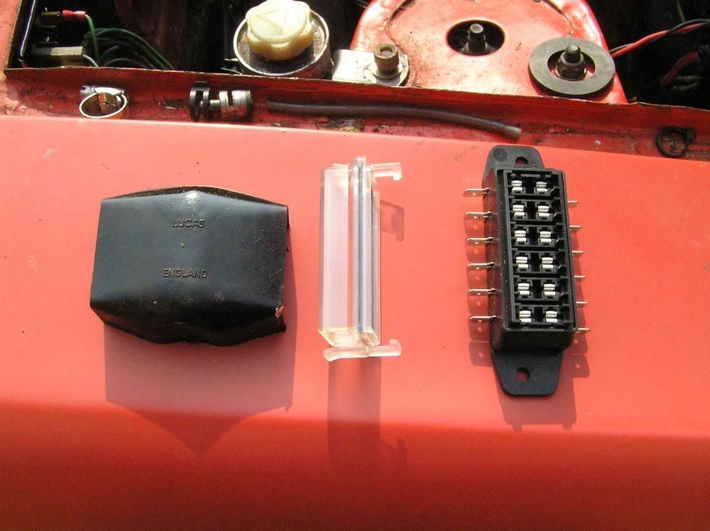
....and some very useful info originally from Tinweevil, identifying which wires correspond to which circuit, with some ratings added by Straylight -Sprintinbits wrote:I bought this off ebay for just under £5 BIN (Incl P+P). Thought I'd post some pics in case anyone else wants one
The black cover on the left is obviously the standard cover and is there to give a size comparison
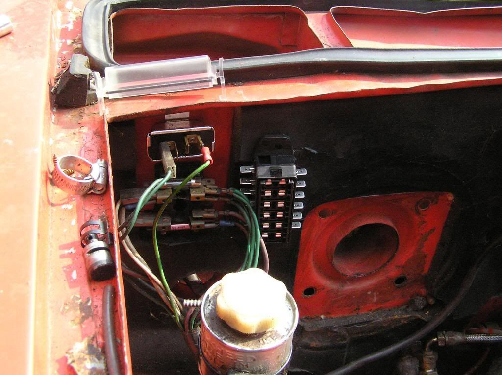
Just resting in position to show size.
It takes normal blade fuses.
The cover has a rubber sealing insert to it and seam a little flimsy but only if you're heavy handed.
Item was:-
http://cgi.ebay.co.uk/ws/eBayISAPI.dll? ... &rd=1&rd=1
The circuits are probably goi to be:-
1, Permanent Live (No Lights)
2, Ignition Live (No Overdrive)
3, Overdrive
4, Dip lights
5, Main Beam
6, Stereo
Other peoples thoughts that may be relevant are -straylight wrote:There are 6 wires on the right side of the box, anybody care to confirm or correct the following? Or add the ratings?
Purple 1:
- Hazard lights 21W x 4 = 84W = 7 Amps
- Cigarette lighter 50W max = 5 Amps (guessing it could be used to power a spotlight !)
- Clock bugger all
- Boot light 2.2 W = 0.18 Amps
- Courtesy light 5W = 0.42 Amps
Total 12.6 Amps
Purple 2:
- Horns ?
- Passing headlight flash 55W x 2 = 110W = 9.2 Amps
Green1:
- Reversing lights 21W x 2 = 42W
- Overdrive ?
Green 2:
- Windscreen wiper park function
Green 3:
- Windscreen wiper
- Windscreen washer
- Heated rear window
- Brake lights 21W x 2
- Blower
- Seatbelt warning
- Tachometer
Green 4:
- Voltage stabiliser which then does:
- Fuel gauge
- Temp gauge
So you could fuse the above groups by just moving wires at the fusebox. Then there is:
Unfused, supplied by a white wire on the left of the fusebox:
- Choke warning
- Handbrake warning
- Fuel warning
- Oil warning
- Brake balance warning
- Voltage gauge
- Ignition circuit
Which could be fused. Other white wire on the left is the feed from the ignition switch. Lastly there is:
Unfused, supplied from the splitter on the positive battery lead:
- All interior illumination
- All headlights
- All side lights
- Number plate illumination
None of my manuals show how fog lights are fed. If you want to break up these groups you need to find the splits in the loom or knit a new one. Draw lots of pictures with dimensions of the runs if you do please.
Tinweevil
"Indicators, wipers and overdrive are all worth seperating. The lights arent fused at all, which is crap" - Jonners
"Got seperate circuits for each of the purple wires and each of the green wires, spread some of that 35 amp load love around into smaller fuses. I'll get busy with the multimeter and work out exactly which parts of the purple and green circuit do what later. For now I can just put in 25 amp fuses" - Straylight
My first problem is that I am confused by the relationship between the wires on the left hand side of the box, and the wires on the right hand side - is the side of the box that each wire is connected relevant?