Page 2 of 2

Re: Setting the carburettor float levels

Posted: Sun Sep 08, 2013 9:04 am
by soe8m
The design is ok if only the carbs are horizontal on the engine so SU is not to blame. The slant manifolds are a bit twisted to have the carbs level. Sometimes the most you can achieve only by fitting the parts the most clockwise way. Carbs can turn a bit around the fixing studs. The washers needed are not much. The needle is next to the swivel point of the float Most of the time it's from zero washer till 1mm max. Just sand a fibre washer to desired size.

Jeroen

Re: Setting the carburettor float levels

Posted: Mon Sep 09, 2013 4:05 am
by Robert 352
A lot more information has come to light since I asked the question at the start of this thread. All of it, I hope leading to a better understanding of how the carburettor system works on the Dolomite engine.

I have been having a problem with the rear carburettor. Occasionally the cover over the float chamber, can be seen to be wet with fuel and this then drips down and forms a pool in the frost plug sitting in the block below. I put this posting up because I have been trying various different combinations in order to find out where this fuel is coming from and to eliminate the problem.

My thinking is as follows.

The engine is running “about normal” and I have achieved a fuel economy of about 29 mpg, which I suspect, suggests that the two carburettors are close to their optimal settings.

I had noted Jeroen’s comments earlier about the relative heights of the jets. I had discussed this with an engine tuner here who has had a lot of experience in tuning triple carburettor set-ups on Jaguars and who acknowledged that Jeroen comments are valid, but sometimes awkward to overcome.

However my belief is the problem I am trying to overcome does not relate to the setting of the jets themselves but has more to do with the float needle valves and perhaps the float chamber cover of the carburettor(s).

One question which remains unanswered, in my mind, is why is the float chamber on the front carburettor vented with its vent tube which runs down behind the alternator (somewhere) and why is the rear carburettor float chamber not vented in a similar manner?

Is the rear carburettor float chamber vented at all?

If it is where is the vent?

If the float chamber cover of my rear carburettor occasionally has fuel pooling on top of it, where is it coming from?

The likely source is that the flexible pipe feeding it was not held on securely and when the float valve was closed the pressure from the fuel pump forced fuel out under the hose clamp.

I have changed that hose (new hose); I have tightened that clamp and not fixed the problem.

This led me to ask the question at the beginning of the thread. What is the correct position of the float valve when the float is resting on the float needle? If I can get an answer to this question then it will tell me whether I have the right float needle assembly.

Here is a photo of two float chamber covers each fitted with the same float and float valve assembly.
20130909-4352Ptw Carburettor cap assemblies.jpg
20130909-4352Ptw Carburettor cap assemblies.jpg (119.39 KiB) Viewed 1628 times
Perhaps I thought, the left hand cover would be machined differently to allow the float to sit higher, that is when inverted back into its correct position it would sit closer to the float chamber cover. (Which would overcome the issues raised by Jeroen)? This photo is somewhat distorted for it shows the float sitting closer to the cover in the left hand picture however when I measure the float height from the body the left hand float sits 5.00mm or 0.1969” away from the cover. The right hand float measures 4.76mm or 0.1805”. The reverse to what I had expected but which tells me that when the holes for the float valves were machined and tapped that there is possibly something like a 0.010” – 0.25mm tolerance in the allowable height on both.

Note!! No vent pipe on the left hand cover.

Jeroen has also provided a very handy link to an earlier thread in which VanIsleSprint quoted some figures from an SU manual. The figures quoted, if I read them correctly, suggest that the floats on these two covers should sit somewhere between 0.062” 1.57mm and 0.187” - 4.87mm. It is clear I have the right needle valve assembly but that on the rear carburettor cover I should remove a washer under it if I want it to sit within the band nominated.

It should in theory be possible to swap the two covers and the carbs should run satisfactorily. I am loathe to try this and risk having fuel spill above the alternator!!

All suggestions gratefully received.

Robert
LH Cover vent

Posted: Mon Sep 09, 2013 5:44 am
by Robert 352
I am feeling a bit daft now for I have located the vent on the left hand float chamber cover.
20130909-4352Ptw LH Carburettor cap assembly.jpg
20130909-4352Ptw LH Carburettor cap assembly.jpg (145.93 KiB) Viewed 1627 times
It simply vents onto the top of the float chamber cover.

Clearly my problem is the float needle valve assembly which is not closing off from time to time. And when it is not closing, it is spilling fuel. So I shall now try different needle valve sets to find a set that seats.

Perhaps I need to go back and check the filter on the top of the fuel pump. However on my initial check there is nothing in the bottom of the float chamber which might suggest that there is some sediment coming through from the tank or the fuel lines or the pump itself.

It is odd though that it does not vent via a spill pipe down below the engine, as does the front carburettor.

Robert

Re: Setting the carburettor float levels

Posted: Mon Sep 09, 2013 10:26 am
by Jon Tilson
Yes that is very odd....

I have seen this on a couple of odd Spits over the years but I think they should all have vent pipes. My 79 example certainly does.

Jonners

Re: Setting the carburettor float levels

Posted: Mon Sep 09, 2013 8:50 pm
by Robert 352
It has been one step at a time!

Having now determined where the fuel is coming from, and establishing that the float levels are sort of right, (They will be fine tuned shortly), I can now get on and deal with the problem of the carburettor spilling fuel which became very evident late yesterday.

The problem is what looks like a fine rust which is, when I put my glasses on and peer into the gloom at the bottom of the carburettor, is evident. Where is it coming from? Well clearly the petrol tank which sat dry for some 25 years, - and was patched at one stage, has a fine film of rust inside. All the fuel lines were cad plated and although I put compressed air through them, when I fitted them back on the car, they could also be shedding flakes of what have you.

I will fit an inline filter today and see whether I can trap the sediment coming through and which has obviously been getting caught under the float needle valve. This would explain the intermittent nature of the flooding.

Thanks gentlemen for your comments. I will get these float levels and settings in the jets right yet.

Robert

Re: Setting the carburettor float levels

Posted: Mon Sep 09, 2013 8:54 pm
by soe8m
Aftermarket fuelpumps can deliver 0,5 bar. An su needle is designed for 0,15-0,20 bar.

Jeroen

Re: Setting the carburettor float levels

Posted: Tue Sep 10, 2013 8:59 am
by minidave
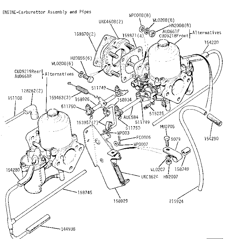
Hi in 1975 parts book it shows front carb with vent pipe but not the rear Dave.

Re: Setting the carburettor float levels

Posted: Tue Sep 10, 2013 1:08 pm
by Mad Mart
minidave wrote:Hi in 1975 parts book it shows front carb with vent pipe but not the rear Dave.
Image

Re: Setting the carburettor float levels

Posted: Sun Sep 22, 2013 4:53 pm
by GrahamFountain
This issue of the front chamber being higher than the jet and the back one being lower is even worse when the engine's in a TR7 - the 7 has a twist in the inlet manifold to compensate for the greater incline on the engine, which is part of why it's different from the 1850 doly one. However, the factory TR7 Sprints just used the Doly manifold - as far as I can see, without washers or owt. So maybee Rick at S&S is right, and the fuel level at the main jet isn't really critical when the engine is running and there's any vacuum in the venturi. Otherwise, there'd be a caveat in the manual about parking on hills and expecting it to start.

Interestingly, all the twin-choke side draught manifolds I've ever seen are also twisted. Suggesting to me that they are actually designed for the TR7 with a 16v engine not the doly.

Re: Setting the carburettor float levels

Posted: Sun Sep 22, 2013 5:00 pm
by Jon Tilson
Maybe thats why the TR7 setup in my dolly produces the most even idling slant 4 engine I know....

I had to sort this issue on a 1500 yesterday. someone had redone the carbs and fitted new float valves....level far too high in fromt carb meant I could
not lean it out enough even with the jet fully up. Had to put a washer under the float valve. First time Ive ever needed to do this.

Float valves were obviously new replacements, so beware of this if you replace yours.

Jonners

Re: Setting the carburettor float levels

Posted: Sun Sep 22, 2013 7:28 pm
by soe8m
The twin choke webers and more "universal" sport carburettors do have the jet in the middle of the float chamber so the fitting angle is not that importand because beer in a glass is alway's level in the exact middle when you strumble with it.

Stromberg did have it and at last SU did discover it too with the HIF.

Jeroen

Re: Setting the carburettor float levels

Posted: Sun Sep 22, 2013 10:07 pm
by GrahamFountain
Don't forget the 1967 Amal concentric: isn't it the fewest moving parts you can have in a proper carb. less than that and it's the Wal Philips "fuel Injector". The Amal would run at 40 degree downdraught angle!

Re: Setting the carburettor float levels

Posted: Mon Sep 23, 2013 9:38 am
by GrahamFountain
Hopefully not too off topic, but while discussing doly carbs, has anyone seen one of these carb link plates on a doly sprint, ever?

Image

Not sure if this photo exagerates it a bit, but you can see the much larger incline on the engin in this picture of a TR7 Sprint.