Re: Taking the Kienzle dash clock apart
Posted: Fri Dec 04, 2020 12:02 am
I've had to give up on the clock mechanism with the yellow second hand as it runs slow with the maximum advance setting on the hair spring. It took a little bravado to pull the second hand out of the clock as I couldn't see what was holding it in. But it turns out it's just a nylon plug and helical winding in a hole in the end of the clock spindle and came out for moderate effort.
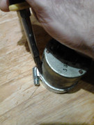
The first photo shows how I used the 65mm jubilee clip to support the front of the chrome ring while I levered the roved over flange up. I did still get some splitting of the ring, but there was less than whoever had done the other clock first and little distortion visible once back in the dash panel.

With the chrome ring off - the rubber seal is badly perished in this one. It might be possible tp replace it with the right diameter silicon rubber O-ring.

With the perspex removed, there's a thin, flat metal ring painted black.

Next is a spring cup for the perspex and black painted metal ring.
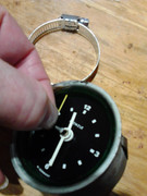
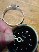
The fifth photo shows me taking the second hand out. This comes out reasonably easily, just pull with a little care.
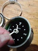
I took the other hands off too, because the hour hand was about half an hour fast with respect to the minute hand. But there's no need to take any of the hands off the front to get the mechanism out if that needs to be repaired. I just did that to show.
This shows the only nut that holds the mechanism in the case once the front ring is off.

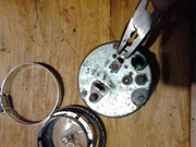
The last photo shows the location of the link that often breaks, so that the points that close as the mechanical clock runs down don't operate the solenoid that winds the clock up and causes the points to open again. I've bridged this link with solder in this one. Though some websites suggest a zener diode should be used. However, it does seem to work with a solder link. You'll just have to forgive the use of pliers: I didn't have a small enough spanner to hand.
Graham
The first photo shows how I used the 65mm jubilee clip to support the front of the chrome ring while I levered the roved over flange up. I did still get some splitting of the ring, but there was less than whoever had done the other clock first and little distortion visible once back in the dash panel.
With the chrome ring off - the rubber seal is badly perished in this one. It might be possible tp replace it with the right diameter silicon rubber O-ring.
With the perspex removed, there's a thin, flat metal ring painted black.
Next is a spring cup for the perspex and black painted metal ring.
The fifth photo shows me taking the second hand out. This comes out reasonably easily, just pull with a little care.
I took the other hands off too, because the hour hand was about half an hour fast with respect to the minute hand. But there's no need to take any of the hands off the front to get the mechanism out if that needs to be repaired. I just did that to show.
This shows the only nut that holds the mechanism in the case once the front ring is off.
The last photo shows the location of the link that often breaks, so that the points that close as the mechanical clock runs down don't operate the solenoid that winds the clock up and causes the points to open again. I've bridged this link with solder in this one. Though some websites suggest a zener diode should be used. However, it does seem to work with a solder link. You'll just have to forgive the use of pliers: I didn't have a small enough spanner to hand.
Graham