Jeroen, everyone,
Thanks for all these replies. End or the road with this (pun intended) - two things :
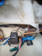
Firstly I got details of how the controller works. Extensive verbiage at end if interested but in short it comes on with ignition and doesn't wait for temp sensor in top pipe to eventually heat up before activating.
I am not an expert on this cars cooling system or any other. Similarly I've never buzzed out the entire electrical system for kicks. But I have enough of an idea and experience to keep it on the road in the face of very little specific professional experience being available in Western Australia. And that is an extra challenge here, makes a mistake or not order the parts first time and you are waiting 2 to 3 weeks for them to turn up.
Weather clearing up and test drives for sure over next 48hrs. Thanks for description, I completely get how the reseal might work but nearly 20yr old seals so hard to be too optimistic.
I would appreciate a clarification of the water cooling flow in the car. A much earlier thread had a diagram someone had done but the link is no longer valid.
My understanding starting at pump cavity, mech pump :
1. water in from bottom rad hose
2. water out from pump cavity to heater, to block and potentially in from the thermo housing bypass tube
3. with stat closed bypass is open and thus water circulates around pump, block, head, manifold, thermo housing repeat
4. with stat open the bypass tube is closed off. Now water goes pump, block, head, manifold, thermo housing, radiator repeat
5. the heater circuit is separate and runs from pump cavity via heater and back through manifold. I don't know if this return combines with the engine circ return or is separate. Either way heats the manifold a bit quicker I presume and of course provides for heater. Possibly it runs in the opposite direction of flow not sure?
6. Finally cut and paste from 2010 tinweevil comment

"A small amount goes to the radiator 'cold' side and returns to the pump uncooled when the stat opens too. Thats the stat housing to rad offside top hose,"
Is all that correct?
With EWP there's no mech pump and no thermostat. So now water goes into pump cavity from EWP and into block and up into bypass tube which is not closed off so :
a. water in from bottom rad hose
b. water out from pump cavity to heater, to block and up into empty thermo housing
c. water still circulates to block, head, manifold and back to thermo housing
d. .....but on reaching thermo housing it rejoins any flow up from the bypass tube.
e. these combined flows go past the temp sensor in the top pipe and into the radiator
f. extent of flow and cooling determined by combination of EWP and controller
g. presume other top hose functions as ever before - some type of pressure relief? With no stat it will be permanently doing ... whatever it does
h. the heater circuit is a bit orphaned. I'm not clear why it gets limited or no flow if left as is. Solutions are i) do nothing, heater not crucial in Aus ii) augment flow with little booster pump, again not clear on flow direction iii) connect heater return previously to thermo housing with new pipe to junction on EWP suction side thereby pulling flow in that direction around heater cct
I believe this will work as described because several people have told me directly that they have done it with no issue at all.
I can see with EWP there is an argument that the bypass tube is now allowing some waterflow to divert away from engine and straight back to radiator.
I don't see an argument where any hot water coming out of the engine skips the rad - this flow will join the flow coming up the bypass tube and all go to the rad
The question is whether the potentially reduced flow from pump cavity to block (due to some diverging up bypass) has any effect on engine cooling.
I can imagine it creates the case for partial restriction of that bypass tube (per someone, Carledo?) to limit that diverging flow but I can also imagine this makes no practical difference (and ref people have it working fine). Furthermore the pump controller is just going to crank up the flow anyway if it senses an issue to list should be self solving. The final argument might be that the bypass tube could be blocked off but is likely work for no benefit
Any of that "logic" make sense?
I'm looking forward to it self sealing so that all of this dialogue is just a note in history
)))
Regards, mark
"
When the ignition is first turned on and/or engine is started, the Digital Controller 'system checks' the EWP®. All the diagnostic functions will be illuminated and the current engine temperature will be displayed. The EWP® will commence operation for approx. 10 seconds which commences the coolant circulation through the engine. At this point the “EWP” insignia/logo will be flashing on and off. There is a built-in five (5) minute ‘window’ for the engine’s coolant temperature to rise above 40°c. If this doesn’t occur the system will ‘sense’ there is a problem and the EWP® and fan will operate at full measure till this temperature is exceeded. In some climatic conditions this may occur and by switching off the engine and restarting, the Controller’s 5-minute built-in timer will restart. It’s expected there will be enough temperature in the coolant at this point for the Controller’s diagnosis to move past this phase on restarting.
The LCD EWP®/Fan Digital Controller supplies a six volt pulse-width-modulation (pwm), (10 seconds on, 30 seconds off) to the EWP® from a cold start until the engine temperature reaches -20°c of the targeted/set temperature. At this point, the Digital Controller then supplies a pwm (10 second on, 10 seconds off) till the engine temp reaches -5°c at which point the Digital Controller will ramp up to full system voltage (13.5v) as and when required searching for and locking onto the targeted/set temperature. At this point the “EWP” insignia/logo on the LCD screen will stop flashing which indicates the EWP® is operating at full flow. This increase in voltage increases the speed/operation of the EWP® and subsequent coolant flow, commensurate with the engine temperature.
The electric fan/s will be deployed at +3°c (+5°f) above your set/targeted temp. The fan insignia on the LCD Screen will begin to rotate.
Once the engine has reached your set/targeted temperature there is an 8°c window in which the EWP® and LCD EWP®/Fan Digital Controller will operate and control engine temperature.
If/when the engine temperature cools -5°C below your targeted/set temperature, the Digital Controller will step back from full system voltage to 6v if necessary and generally will revert to pwm when ram air through the radiators increases. At this point the “EWP” insignia/logo on the LCD screen will recommence flashing.
"