Page 1 of 7
Start of new project.
Posted: Tue Nov 29, 2011 10:30 pm
by soe8m
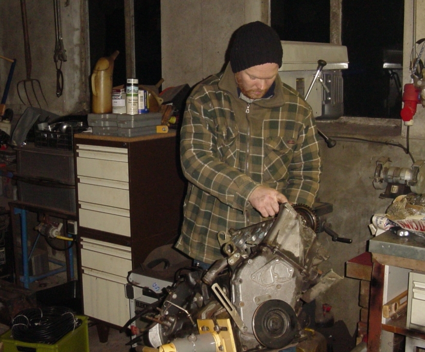
Just started tonight on my new engine. My current daily driver isn't that good anymore so a new engine.
I could take the current engine apart but then i have to go by bus to my work and that's no option. And when there's a lot of snow outside soon it would be very frustrating not to have a running rwd dolomite on the parkingspace.
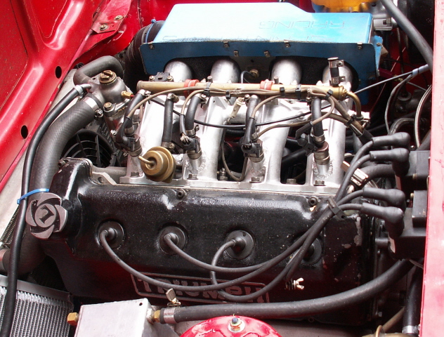
The one i'm going to use is an engine that i drove in another car for about 10.000 miles and was totally std, so std cams and hs6's. Only optimized and had about 135hp on the rearwheels and a crazy compression ratio of 1:11,5. It could only run on octane 98 or higher. The first thing i did tonight was change the camshaft for a st rally gp2 cam, just to see if it was possible and the valves did not tough the pistons. This was all ok. The next thing is to take it apart for a check. This engine is becoming fuel injection on a weber manifold. I'm not going to use weber type throttlebodies but want to fit the injectors in the manifold, just in front of the inlet valves. Will keep you informed.
It was not that warm in the shed but this way i have the same working conditions as the ST guy's at Abingdon at the time and have the same tolerances measured.

- camshaft.JPG (468.48 KiB) Viewed 10567 times
Re: Start of new project.
Posted: Tue Nov 29, 2011 11:02 pm
by Oli_88
Very very interested in how your manifold turns out, I had similar thoughts circling in my head.
Though unlike yourself, I lack err, pretty much everything to make it a reality.

"Know ones limits master Wayne." etc.
Re: Start of new project.
Posted: Mon Dec 05, 2011 10:44 pm
by soe8m
Little update:
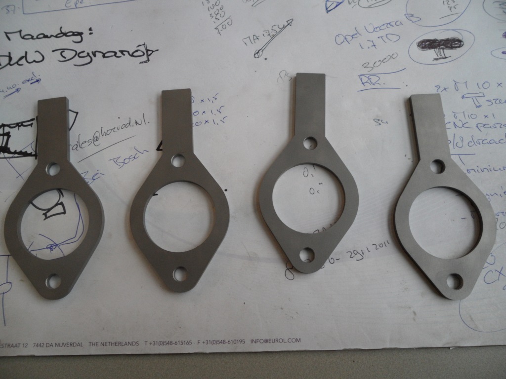
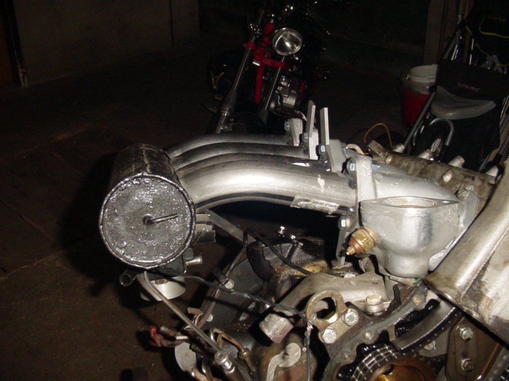
Time for some pipe bending. I have determined the location of the plenum, a tr7 one. This set up should fit into the bay and have space enough to fit the injection rail between the plenum and manifold. To the end of this week i will cut some flanges where the pipes are going to be weld on.
- fuel1.JPG (435.92 KiB) Viewed 10380 times
- fuel2.JPG (423.65 KiB) Viewed 10378 times
- fuel3.JPG (456.98 KiB) Viewed 10377 times
Re: Start of new project.
Posted: Tue Dec 06, 2011 4:18 am
by SPRINTPARTS
Here is how my EFI set up is done. I originally made it back in the late 1990's and would probably do it different if I was doing it again, but it still works fine.
[img]
- EFIquad.jpg (266.7 KiB) Viewed 10332 times
[/img]
And here is a twin throttle body set up
[img]
- EFIquad.jpg (266.7 KiB) Viewed 10332 times
[/img]
good luck with the build.
Mark
Re: Start of new project.
Posted: Thu Dec 08, 2011 1:44 am
by Hans ten Broeke
Have done that 15 years ago with good results. car is still running fine, very good fuel economy to.
Used Weber 40mm throttle body's, pump and sensors, DTA programmable management and missing tooth wheel direct behind the front pulley.
Took the distributor of and used only the bearing part to support the oil pump sprocket, 4 pole dis ignition.
6 Sept 1997 (Diana's Funeral) we went to Sodid somewhere north of London and had a technical price for it, and the long distance award.
Only some old pictures digi was not that wide spread those days.
Hans


Re: Start of new project.
Posted: Thu Dec 08, 2011 11:51 am
by soe8m
I would like to have one throttlevalve that's why i did choose this setup. Also the injectors in the manifold, as close as possible to the inletvalves.
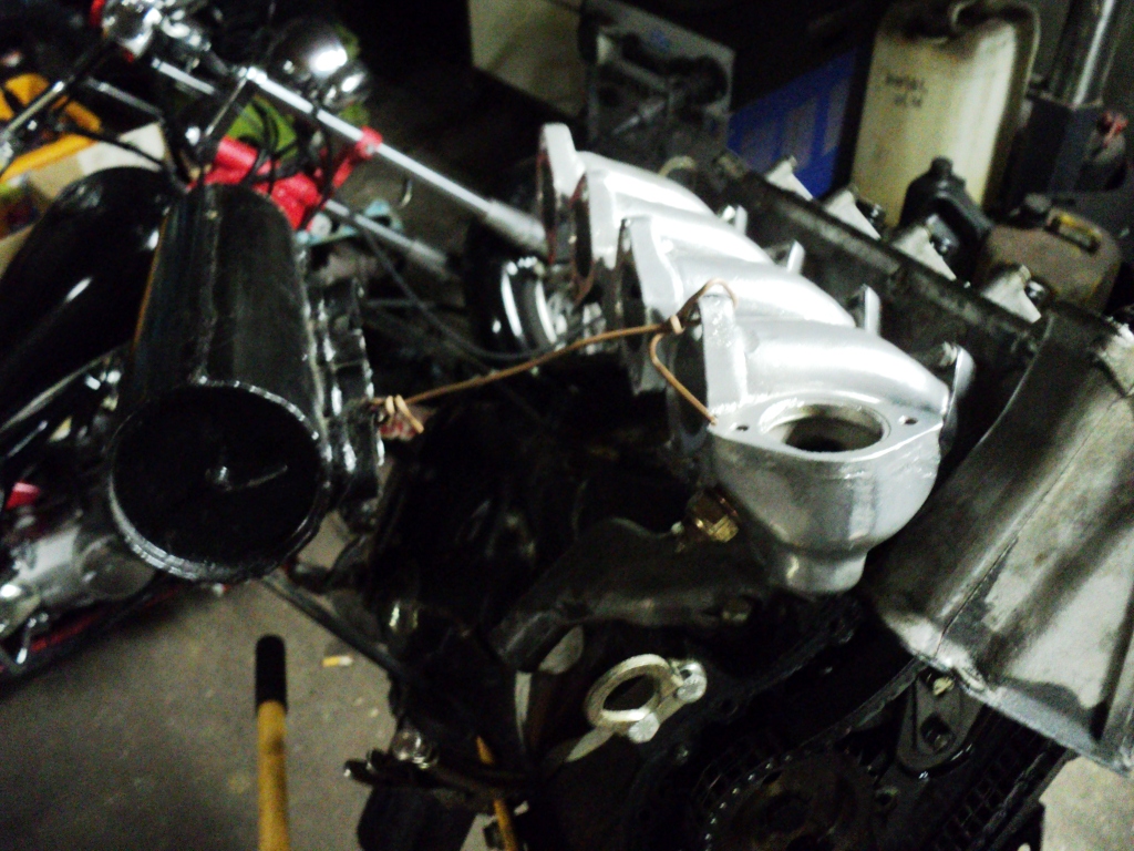
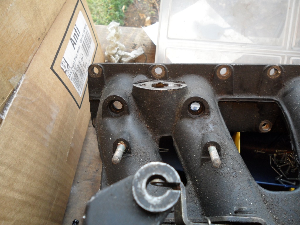
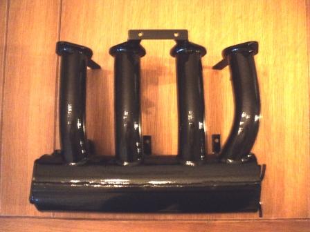
I'm going to weld the bulges of a jag xj6 on the manifold. These can accept the Bosch L jetronic injectors that are in the jag and tr7.
The flanges are on the inletmanifold/plenum. The extensions are going to be bend 90 degrees. Two on the upper side to fit the fuel rail to and two on the lower side to have the wiring loom attached to.
Jeroen
- adapter.JPG (235.49 KiB) Viewed 10121 times
- flange.JPG (187.68 KiB) Viewed 10109 times
Re: Start of new project.
Posted: Tue Dec 13, 2011 10:52 pm
by soe8m
Little update:
I have about 2 hours a week time to spend on this one so a little progress.
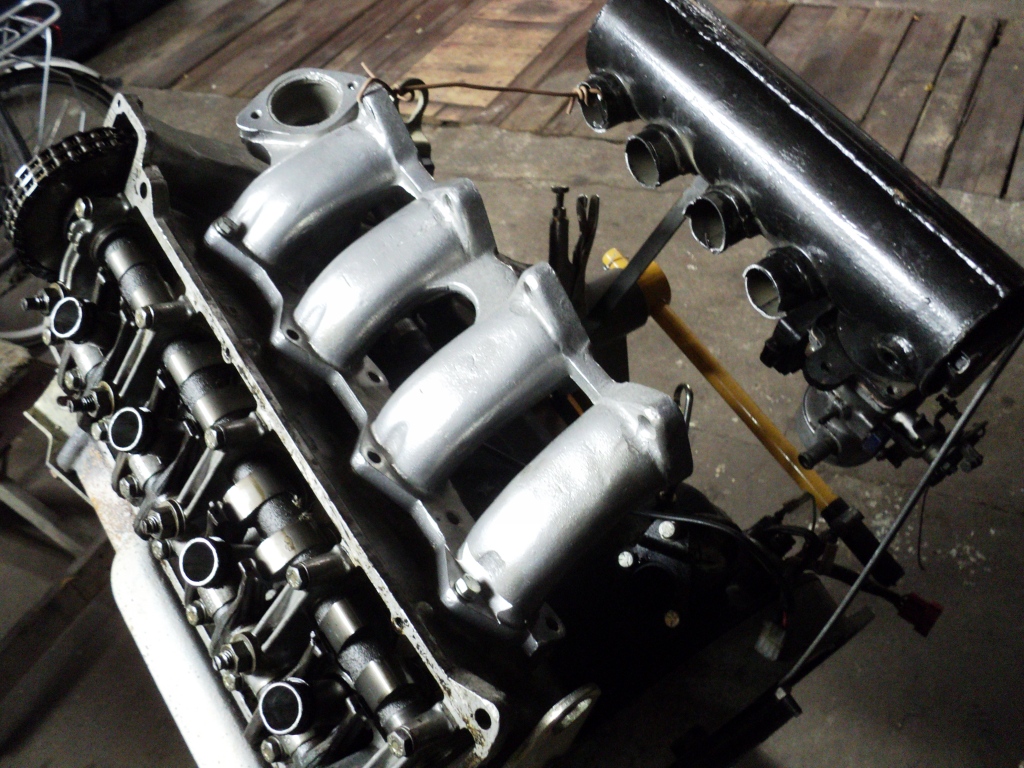
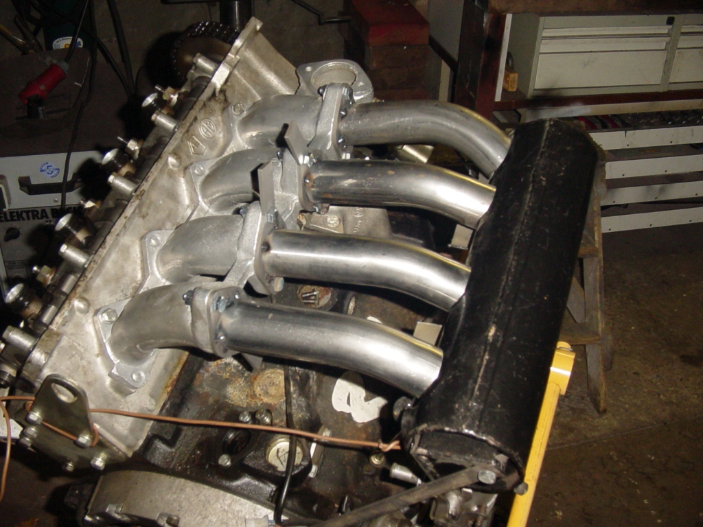
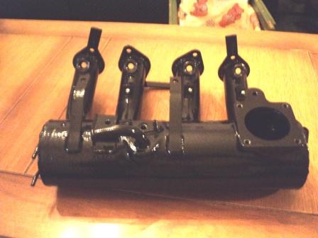
The flanges are attached and the tubes welded on. They are 30 degrees bend and the first one 45. This to have all the curves the same just for the looks because this one does turn back a little also. I could have moved the plenum a bit forwards to have 4 identical pipes but the plenum has to be on this exact position. This engine replaces my LPG fuel injected 1850 that has run about 260.000km now and is the last 2 months on 3 cylinders. The Impreza sound.
Having it this way i do not have to modify the airflowmetre tube and the wiring loom can also stay the same.
Jeroen
- plenum1.JPG (344.59 KiB) Viewed 9915 times
- plenum2.JPG (312.35 KiB) Viewed 9903 times
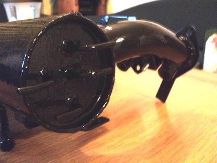
And this is in a few weeks the most famous chain tensioner. it will be know the rest of it's life as THE HYDROLIC TENSIONER.

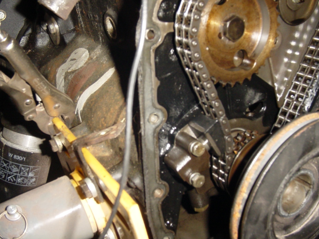
- hydrolic tensioner!!!.JPG (325.07 KiB) Viewed 9872 times
Re: Start of new project.
Posted: Mon Jan 30, 2012 10:16 pm
by soe8m
Some updates with bad pictures:
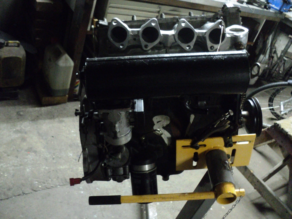
The plan has changed a bit. The plenum is ready and has now the petrol injectors in it. The first idea was to have the injectors on the inlet manifold but there's not enough space for petrol and LPG injectors so the petrol's had to move to the plenum. Not the most ideal but it's just for starting or driving with an empty LPG tank. For the clean look i have fitted the injectors and the fuel rail under the plenum so the tubes stay visible and not much hosing over the engine. The engine block is very clean now and is being skimmed about 0,3mm for even more compression. This engine block is already modified, the cooling and oilchannels but will post pictures later. A genuine Ford hardened oilpump driveshaft is also in da house.
The head is matched with the inlet manifold and doweled to have it alway's on the right spot. The seats are modified for LPG and the inlet ports widened. The only thing to do is the head doweling to the engine block when everything comes back from the machineshop.
The engine mountings are now going to have their most ultimate modification. A few years now i have my subframes modified to two angeled mountings so the oilpump cannot tough the steering rack. 1850 wise but then with a sprint subframe and mountings. The thing to do tomorrow is to fabricate whole new brackets with round rubbers in it, like the gp2 sprints and almost all gp4 escorts. This way the engine cannot move or rotate as much.
The pictures are from the old 1850 engine with a temporary sprint head just to try and decide the height of the engine. The engine was very high in the car because of sump protection but with a sprint head it has to be lowered again.
Jeroen
- plenum1.JPG (42.09 KiB) Viewed 9393 times
- plenum2.JPG (40.49 KiB) Viewed 9358 times
- plenum3.JPG (38.87 KiB) Viewed 9342 times
Re: Start of new project.
Posted: Mon Jan 30, 2012 10:17 pm
by soe8m
Re: Start of new project.
Posted: Mon Jan 30, 2012 10:54 pm
by Hans ten Broeke
Oh lordy lordy, my poor dyno.
Still knowing what his old 1850on LPG did put out, this will pretty much more I expect.
BDW I wouldn't be surprised that with all this compression the engine will even take a 3' fuel, DIESEL
Hans
Re: Start of new project.
Posted: Mon Jan 30, 2012 11:43 pm
by trackerjack
Good stuff our Netherland friends.

Re: Start of new project.
Posted: Tue Feb 14, 2012 7:23 pm
by soe8m
Hello, little update:
The engineblock is almost ready. Only the head dowels must go in and that will be Saturday.
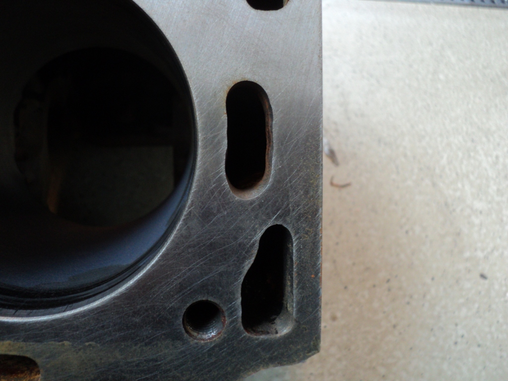
At first the deck is skimmed 0,3mm and the compression ratio will be now 1:12. The deck is skimmed on a special device that is connected on the main bearing part of the block. Dolomite engines are never drilled straight and this way the deck is flush with the crankshaft bore. The piston are now evenly above the deck. Before there was a difference from about 0,15mm. The first was straight with the deck and the fourth was 0,15 below. It can also be seen on the jackshaft keep plates. There's alway's wear on 60% of the half circle so the jackshafts are not 90 degrees in line but alway's a bit off.
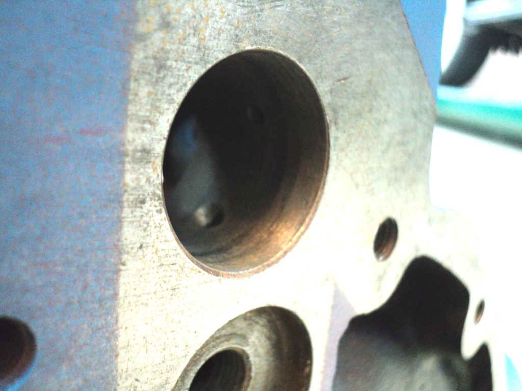
I did want a better oilflow to the camshaft and decided to have an extra external oilpipe to the head on the rear of the engine and head. The rear jackshaft bearing would be my take off. The oilflow at the front is pulsating to the head. This is to maintain good lubrication for the bottom end. I'm going to make a little flat spot on the rear jackshaft journal, exactly timed with the front so at the same time oil is pushed from two way's to the camshaft and rocker shaft. This is why the external oilfeed kits are bugger because the direct oilflow goes to the rockershaft giving too much oil what's intended for the bottom end. The pulsating on the ohc 4 and 6 cyl is by a flat spot on the rear of the camshaft.
When measuring the exact hole for the take of i discovered that the main feed is not lined up with the groove in the jackshaft. The overlap was 0,8mm. The oilbore is about 4,5mm and the groove is 4,75mm. You can see the darker part where the groove is. I did make the main oilhole a bit oval towards the groove to have more oil there for total lubrication of that journal and for the distributor/oilpump gear what also gets here the oil from.
I opened up the waterway's to match my base head gasket. This gasket is also on the head and so the waterway's are matched.
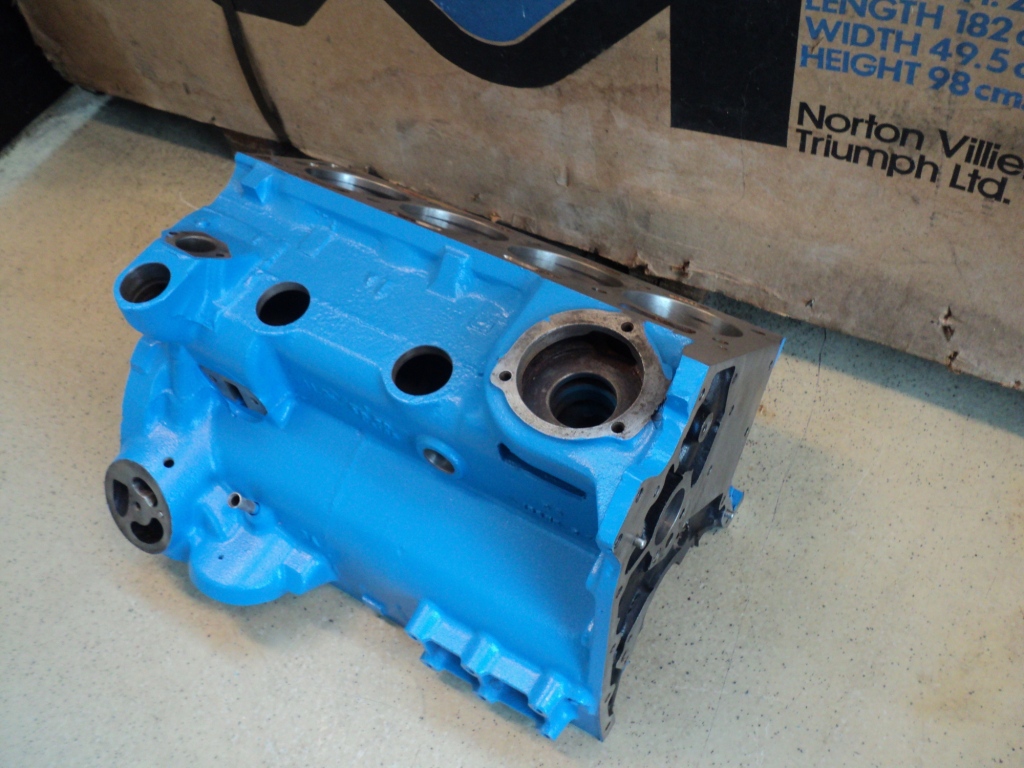
- engine0.JPG (328.27 KiB) Viewed 8953 times
- engine1.JPG (355.92 KiB) Viewed 9014 times
- engine3.JPG (305.75 KiB) Viewed 8937 times
Re: Start of new project.
Posted: Tue Feb 14, 2012 7:32 pm
by soe8m
Re: Start of new project.
Posted: Tue Feb 14, 2012 7:43 pm
by soe8m
Re: Start of new project.
Posted: Wed Feb 15, 2012 7:59 pm
by TahitiSPRINT
Ha Jeroen, very impressive! I'm jealous:-)
Now the block is save, how many revs are you planning to use? And with the big compression, you need a cam with a big overlap. Does the LPG cope with that, so minimum chanches on back-fire?
I'm curious to the power output, I'm sure you'll beat your previous record;-)
Groeten,