Hi, please could somebody advise how to wire up :-
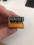
1. Original style Kenlowe fan switch with 4 pins.
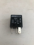
2. Relay with pins 1, 2, 3, 4, 5.
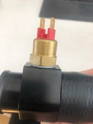
3. Thermostatic switch with 2 pins.
Thanks, Richard

| The Triumph Dolomite Club - Discussion Forum http://forum.triumphdolomite.co.uk/ |
|
| Kenlowe fan override switch, relay and thermostatic switch http://forum.triumphdolomite.co.uk/viewtopic.php?t=36885 |
Page 1 of 1 |
| Author: | RichardHyde [ Thu Sep 16, 2021 12:22 pm ] |
| Post subject: | Kenlowe fan override switch, relay and thermostatic switch |
Hi, please could somebody advise how to wire up :- 1. Original style Kenlowe fan switch with 4 pins. 2. Relay with pins 1, 2, 3, 4, 5. 3. Thermostatic switch with 2 pins. Thanks, Richard
|
|
| Author: | Bumpa [ Thu Sep 16, 2021 4:30 pm ] | ||
| Post subject: | Re: Kenlowe fan override switch, relay and thermostatic switch | ||
I found this on a Triumph TR site when I was asking the same question. Hope it helps.
|
|||
| Author: | new to this [ Thu Sep 16, 2021 5:25 pm ] |
| Post subject: | Re: Kenlowe fan override switch, relay and thermostatic switch |
Ive got the same thing to wire ( fan ) but was going to use the choke switch as the over ride,not sure if the switch contacts are up to it ? |
|
| Author: | Mad Mart [ Thu Sep 16, 2021 6:05 pm ] |
| Post subject: | Re: Kenlowe fan override switch, relay and thermostatic switch |
With your relay I would suggest terminal 1 was equal to terminal 85 and 2 equal to 86. |
|
| Author: | Bumpa [ Thu Sep 16, 2021 8:03 pm ] |
| Post subject: | Re: Kenlowe fan override switch, relay and thermostatic switch |
I hadn't noticed that the relay in Richard's photo wasn't numbered in the conventional manner. I've never seen one numbered like that. |
|
| Author: | soe8m [ Thu Sep 16, 2021 11:22 pm ] |
| Post subject: | Re: Kenlowe fan override switch, relay and thermostatic switch |
85 is ground and 86 positive... Jeroen |
|
| Author: | Carledo [ Fri Sep 17, 2021 9:50 pm ] |
| Post subject: | Re: Kenlowe fan override switch, relay and thermostatic switch |
Quote:
Ive got the same thing to wire ( fan ) but was going to use the choke switch as the over ride,not sure if the switch contacts are up to it ?
Choke switch? You mean that daft little thing that (in theory) puts the choke light on which clips round the choke cable?It can probably handle the current since it's only switching the relay, but it won't do the job since it's a spring loaded "push to make" switch except it's actually push to open, the default position is on! Rather like a brake light switch, but smaller. I guess the thinking is to use the choke warning light, redundant on an EFI car, to represent the fan over-ride. I've used mine for the "Sport Mode" warning light on the transmission, by the same bit of lateral thinking. Be aware that the warning light is ign live powered so the switch is earthed. Changing this to earth inside the warning light display is tedious and difficult, but can be done. Ask me how I know! I did the mod then found out I needn't have bothered as the sport mode light wire needs power, not earth! This mistake fried the trans ECU and I had to buy another, we live and learn! Steve |
|
| Author: | naskeet [ Sat Sep 18, 2021 6:53 pm ] |
| Post subject: | Re: Kenlowe fan override switch, relay and thermostatic switch |
Quote:
I hadn't noticed that the relay in Richard's photo wasn't numbered in the conventional manner. I've never seen one numbered like that.
Conventions vary from one country to another! It was one of the objectives of the European Union to standardise such things. The relay terminal labels 30, 85, 86 & 87 are part of the German DIN standard for automotive electrical terminal labels, with which I am relatively familiar, given that my other vehicle is a 1973 VW "1600" Type 2 Westfalia Continental motor-caravan. I think I still have my Kenlowe "Thermatic" fan literature and wiring diagrams at home; which date from circa 1982. |
|
| Author: | new to this [ Sat Sep 18, 2021 9:41 pm ] |
| Post subject: | Re: Kenlowe fan override switch, relay and thermostatic switch |
Quote: Quote:
Ive got the same thing to wire ( fan ) but was going to use the choke switch as the over ride,not sure if the switch contacts are up to it ?
Choke switch? You mean that daft little thing that (in theory) puts the choke light on which clips round the choke cable?It can probably handle the current since it's only switching the relay, but it won't do the job since it's a spring loaded "push to make" switch except it's actually push to open, the default position is on! Rather like a brake light switch, but smaller. I guess the thinking is to use the choke warning light, redundant on an EFI car, to represent the fan over-ride. I've used mine for the "Sport Mode" warning light on the transmission, by the same bit of lateral thinking. Be aware that the warning light is ign live powered so the switch is earthed. Changing this to earth inside the warning light display is tedious and difficult, but can be done. Ask me how I know! I did the mod then found out I needn't have bothered as the sport mode light wire needs power, not earth! This mistake fried the trans ECU and I had to buy another, we live and learn! Steve Dave |
|
| Author: | RichardHyde [ Sat Oct 02, 2021 7:29 am ] |
| Post subject: | Re: Kenlowe fan override switch, relay and thermostatic switch |
With Jeroen’s help, I’ve done this diagram for future reference. Cheers Jeroen !! 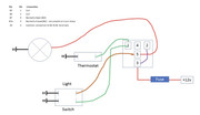
|
|
| Author: | naskeet [ Wed Oct 06, 2021 7:33 pm ] |
| Post subject: | Re: Kenlowe fan override switch, relay and thermostatic switch |
Quote:
With Jeroen’s help, I’ve done this diagram for future reference.
I am still trying to fathom what the rectangle with the labelled boxes 1, 2, 3, 4 & 5 represent!?! Cheers Jeroen !!
I presume the big circle with the St. Andrew's cross inside represents the fan motor!?! |
|
| Author: | Mad Mart [ Thu Oct 07, 2021 12:43 am ] |
| Post subject: | Re: Kenlowe fan override switch, relay and thermostatic switch |
Have a look here... https://www.12voltplanet.co.uk/relay-guide.html Yes, the circle with the cross is the fan. |
|
| Author: | RichardHyde [ Thu Oct 07, 2021 9:52 am ] |
| Post subject: | Re: Kenlowe fan override switch, relay and thermostatic switch |
In the top left corner of the diagram, I’ve included the mapping from pins 1,2,3,4,5 to the DIN 85,86,30,87a,87. I think the 12VoltPlant website says 1,2,3,4,5 followed by DIN pins in numeric order eg 30,85,86,87,87a which is incorrect. |
|
| Page 1 of 1 | All times are UTC+01:00 |
| Powered by phpBB® Forum Software © phpBB Limited https://www.phpbb.com/ |
|