Page 1 of 2
Power to the Coil
Posted: Tue May 24, 2022 2:40 pm
by jlan1978
Hi all
I have a sprint which was running and starting fine. I went to fit the little electronic ignition instead of the points, once fitted the car would not start so I fitted new points and condenser back on the car and still on joy. Its appears I have no power going to the coil. I've checked the Red RPM wire that also connects to the coil an this has 12V, also all the fuses look ok and connecters on the box have 12v.
Am i right in thinking trace the coils wires through the loom to check if I have a bad connection?
Any direction is greatly appreciated.
Joe
Re: Power to the Coil
Posted: Tue May 24, 2022 7:07 pm
by GrahamFountain
The supply to the coil shouldn't be fused. It should come straight off the ignition switch through the ballast resistor. And there should also be a wire from the starter solenoid output to supply 12v to the coil while the starter motor is cranking. So if it turns over, then the coil should be powered, even if the connection through the ballast resistor is broken. In which case, it should fire till the key returns to the run position. But then, that white and yellow wire from the starter falls off a lot on mine.
Here's the ignition circuit part of the wiring diagram.
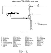
Graham
Re: Power to the Coil
Posted: Tue May 24, 2022 8:11 pm
by jlan1978
Hi Graham
Thanks that is helpful. I am very new to this and trying to learn so would you mind answering some more questions I have, just i don't fully understand.
1 There are two wires coming from the loom they are old but look yellow and white, one is connected to the Coil Positive the other the coil negative. The Coil is a 12v with internal ballast. So when i have the ignition on and put a mutimeter to the positive wire i get no volts reading. Are you saying this will only show power when the starter motor is engaged/spun?
2 There is a red wire that looks is the RPM wire coming from Dash/bulkhead, this is also connected to the Coil Positive, When you say it should come straight off the ignition switch through the ballast resistor is this it? I have power here which would rule out any issue form the ignition switch side?
Thanks
Joe
Re: Power to the Coil
Posted: Tue May 24, 2022 10:50 pm
by GrahamFountain
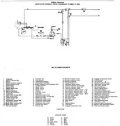
I did forget to ask if yours was before or after commissioning number 15000. Sorry.
So it sounds like this diagram is more applicable to yours, but you have an aftermarket coil. It's also possible there have been some other modifications to the wiring. So it won't be exactly right.
From the diagrams, the coil -ve should have a pair of white and slate wires connected to it: one to the points and one to the tacho and one to the points. However, all the points I've seen have a black wire to be connected to the -ve of the coil, where they are long enough. Where they aren't long enough, a length of any colour might be used to bridge the gap.
The coil +ve should have two wires:
One wire to the +ve of your 12v coil should be a white and yellow wire from the starter solenoid. That's the one that supplies 12v to the +ve side of the coil, and bypasses the ballast resistor, when the engine is starting. If you have a 12v coil, then that wire is mostly redundant. It might still help a bit, because it bypasses the ignition switch.
That wire from the starter solenoid just boost the voltage to the top of the coil to help starting. But with a 12v coil, it shouldn't make any real difference when everything else is as it should be. So, essentially, it's redundant.
The other wire to the +ve of your 12v coil should replace the wire from the external ballast resistor, and comes from the ignition switch. It could be nearly any colour. But, assuming the original white wire direct from the ignition switch is long enough, it could just be that. I have to assume cos I don't remember how the later resistors and coils are wired.
So there should be 12v from the ignition switch in run and start positions, and 12v from the starter solenoid when the ignition switch is in the start position.
But, if I was tracing this fault, I would start by disconnecting the wire to the points from the coil, and checking it's earthed when the points are closed and not earthed when the points are open.
I'd then disconnect the wires to the +ve side of the coil, and check one of them has 12v with the ignition switch in the start and run positions.
With just those two wires, from switch and points, connected to the coil, and working like that, it should start and run.
Graham
Re: Power to the Coil
Posted: Wed May 25, 2022 12:26 am
by Carledo
Just to recap on Graham's main point here. Someone, sometime has been at the wiring as there are NO red wires in the original ignition system. In ALL Lucas wiring, the colour code red denotes sidelight wires and nothing else!
You are just going to have to do this the hard way, tracking the wires back to source and take nothing for granted!
One thing that may help, is that most folk who don't trust the ballast system (there's nothing wrong with it, just some folk think it's unreliable) will fit a 12v coil, disconnect the original pink/white (up to VA 15000) or yellow/white (VA15000>) lead to the coil and substitute a direct feed to the coil +ve, usually from the unfused (white wire) ignition live side of the fusebox. This can, of course, be any colour the installer fancies (or has lying around) but it's amazing what a popular choice red is! This same point is also used to power an electronic ignition module with 12v when keeping a ballasted system running with EI. When using EI of either Magnetronic or Accuspark/Britpart et al make, this wire is usually red going to the module in the dizzy.
I have a Magnetronic equipped Sprint in my care presently which has had the ballast bypassed in just the way I described above, guess what colour wire was used! I'll take some pics tomorrow when there's daylight.
Steve
Re: Power to the Coil
Posted: Wed May 25, 2022 8:18 am
by GrahamFountain
Me, I like the separate ballast resistor. I didn't know you could get coils with internal resistors - I thought the 12V ones were just like the 6V ones with more windings for a bigger mutual inductance value (M) for a bigger M.di/dt and a bigger spark.
I like the separate ballast resistor on a 6V coil, as it allows the spark to be boosted during start, in part at least, to compensate for the load from the starter motor pulling the battery voltage down.
But if you are lucky, you won't have to trace the wires inside the loom. Since it worked before, the problem is just to identify how it was wired up - if that's what's gone wrong -, and wire it the same. So it should be possible to infer where the important wires go from what they do. I know the wire from the points is obvious on my car. But I realize I'm making an assumption that true for yours as well.
The only other wire that essential to identify for the car to run is the one that, ultimately, comes from the ignition switch. And that can be inferred from it having 12V on it when the switch is in run and start positions, and not radio and off. Working out which drives the tacho from the -ve side of the coil, which is useful, and which comes from the starter solenoid to the +ve side, and isn't much use with a 12V coil, should be easy by trial and error.
If you get that sorted, and the points are earthing and not earthing the bottom of the coil as they should, and it still don't run, there's another problem. The question then would be, did you have the distributor out to do the swap of points to electronic ignition and back? And are you certain it went back right? I've put the distributor back 180 deg out when I've left my thinking head somewhere. And then I've struggled to see what I've done wrong. And enough times to realize it's not that hard if you get distracted. You then have to take the trouble to check it's firing TDC compression, not TDC exhaust.
Graham
Re: Power to the Coil
Posted: Wed May 25, 2022 9:41 am
by soe8m
There are no ignition coils with internal ballast resistor.
Both ballasted or unballasted coils are 12v coils, for 12v cars.
Measure what coil you have and then you know how to connect. 3Ohm primary unballasted and around 1,5Ohm for a ballasted system coil. Measure and know because its crucial to know how to connect. Also measure your testleads and take this value of the total measured.
The added red wire can also be a takeoff. The coil is a popular point to take of 12v feeds or on a ballasted system a 9v feed for the unknowing..
You have as a feed a white/pink AND a white/yellow or a white/yellow only. These or this is fitted to coil pos.
Sometimes the wires to the coil are in a pvc wiring sleeve. Just seeing a white/yellow can also mean a missing white/pink because of a cut too short white/pink wire somewhere in that sleeve.
The white/slate is the rev counter and connects to coil neg as are the points.
As Graham describes points must ground to the engine when closed and no ground when open.
Measure, know connect and run.
Jeroen
Re: Power to the Coil
Posted: Wed May 25, 2022 12:04 pm
by GrahamFountain
soe8m wrote: ↑Wed May 25, 2022 9:41 am
There are no ignition coils with internal ballast resistor.
Both ballasted or unballasted coils are 12v coils, for 12v cars.
Interesting then that this
https://howtosguru.com/how-do-you-tell- ... -resistor/ and several other sites go into some detail on how to identify these non-existent internally ballasted coils. However, I wasn't certain that just because I've never seen one, they cannot exist.
Also, an (externally) ballasted coil on a 12V car won't normally have 12V (or 13V or 14V or whatever the supply voltage actually is) on the coil when running normally. Whether it's nominally 6V or no, that's only my shorthand for a coil where the coil itself is normally operating at a substantially lower voltage than the car's supply. So, sorry for the imprecision.
And like was said, the car ran before. So I'd just identify how the coil as it was wired when it ran before; not worry overmuch about precisely what PO's have done with the wiring. That might well be a bit Heath-Robinson, but it worked. So re-connecting it that way is the quick way to move forward in isolating the problem.
If it's wired as it was when it ran, but doesn't, then there's another problem.
Graham
Re: Power to the Coil
Posted: Wed May 25, 2022 2:18 pm
by soe8m
Graham, don't start making yourself a fool again.
There are no coils with internal resistors. As in your posts about the rubber gland and washer, not all you do read on the internet is true.
There is a difference in resistance in coils but they don't have resistors in them. For a 6 volt car you have a 6 volt coil and for a 12v car you have a 12v ballasted type or a 12v unballasted type. The 6 volt coils for 6 volt cars have about the same primary resistance and would work as these won't damage anything because of the same current through but the secondary resistance is different. But fitting such a 6 volt coil doesn't mean that there's also 6 volt on it on a 12v ballasted system.
Measuring the voltage at the coil on a ballasted system you read around 9 volts but you probably can find an article or forum post that says not.
The most important is to know what coil you have and start from there.
Good quality points can handle the higher current a long time by a wrong coil fitted but the current new ones do melt the plastic guides and the plastic cam follower when the current switched is too high. The point will short or won't open because of the melted cam guide making no spark.
Some cheap electronic ignitions do fry themselves immediately by the too high current by a wrong coil just by switching ignition on.
So before even proceeding find the original feed and know what coil you have.
Then measure or investigate further when you know the correct parts are fitted.
Jeroen
Re: Power to the Coil
Posted: Wed May 25, 2022 3:00 pm
by Mad Mart
The coils differ in resistance because of the amount and/or diameter of the coils of wire within the coil. It's similar to the ballast resister, it isn't a resistor component, as such, it is just a length of wire which measures approx. 1.5 Ohms resistance. I have actually measured the resistance when I dismantled a loom and the wire itself was either 4 or 5 feet long.
Re: Power to the Coil
Posted: Wed May 25, 2022 3:38 pm
by GrahamFountain
soe8m wrote: ↑Wed May 25, 2022 2:18 pm
Graham, don't start making yourself a fool again.
Jeroen
I expect it's pointless to say there's no need to get offensive again.
Graham
Re: Power to the Coil
Posted: Wed May 25, 2022 4:22 pm
by jlan1978
Afternoon All
Ok i fitted the new coil reconnected all wires back up as before and the car started, it was very lumpy would barely tickover, when i tried starting again it struggled, so my next step is to check the points and then timing. Is 0,4mm point gaps correct?
Also any advice on what electronic ignition to buy? As the one i got hasn't worked at all. Are there various distributer models that can effect if an electronic ignition works? I know on my Dads P6 V8 after a certain year the distributor was different and the electronic ignition was useless on the older one but worked first time on the year later model distriutor.
Thanks for all the help and guidance, Im' learning loads.
Re: Power to the Coil
Posted: Wed May 25, 2022 5:17 pm
by tangocharlie1
Depends on your budget and there are various people on this site that can will give you advice on what electronic ignition to use and which ones you should avoid, i can only speak about my car, it has been fitted with the lumenitition magnatronic unit for many years (at least 15), all i will say is i fitted the matching coil that was recommended to be fitted alongside the unit and never had a problem.
Re: Power to the Coil
Posted: Wed May 25, 2022 5:18 pm
by soe8m
Soooo,
For the last time, what is the resistance of the coil and how is it connected? Inferior ballasted type coils without their resistor can go faulty easily as there's too much current through their windings. A red Bosch is that robust that these don't fail but the new Lucas Chinese ones don't last this way.
It's for your own good as when it's wrong no points will survive and every electronic ignition will instantly fry when connected.
You are new but the first thing to learn is that parts that are supplied and told these will fit are most of the time the wrong part. Measure and know what you have. Then start from there.
Jeroen
Not my pic but this is what I see regulary by a wrong coil fitted.

Re: Power to the Coil
Posted: Wed May 25, 2022 9:17 pm
by jlan1978
Jeroen come on please, can we communicate without the adolescent tone and attitude?
Can you understand that we have people on here with 30 years experience versus people with 30 days experience. If this isn't taken into account its a race to the bottom in regard the quality and sincerity of this forum and Club, and worse of all it will discourage people from taking part, trying to learning and preserving the cars we all love.
Myself I am closer to the 30 days experience level so I am going to struggle with certain questions and points during the communication. This isn't meant to waste people's time, patience and energy its just I don't understand.
I get what you are saying regarding the parts and measuring and I'm putting one jigsaw piece in at a time. Also if we cannot trust suppliers and their knowledge and advice ??
Regarding your questions:
The resistance of the coil I have no idea how to test this so i will need to research and come back on that.
The coil is connected as follows, One red wire coming from the Fuse box to the + side giving 12v power, one wire coming from the loom white in color to the + side.
One wire coming from the loom looks white to the - side, then the distributor wire from the condenser connected to the - side.
The Coil, Points and Condenser are Lucas from Rimmers.
Again your help, time and experience is genuinely appreciated
Joe