I'm in the middle of sorting out this area on my 1850HL the problem I have is due to previous bodging and corrosion I'm struggling understanding exactly what I'm trying to replicate.
I am quite fortunate to have a NOS panel which my parts book says should not exist as its NSS, be that as it may I've got one and it answers part of the question but raises more. Panel in question us the one that forms the rearward part of the inner wing, onto which the A Pillar is spot welded to, parcel shelf brackets bolt to etc. It is obvious that this panel is sandwiched between the inner and outer sills on their top edge and provides a mounting for the baffle plate up to a point just below the box section bracing panel which has a plate on which takes over and supports the upper part of the baffle. So far so good.
What I can't work out it what the arrangements are from the point of the top of the inner and outer sill should be down over. As far as I can see the inner sill stops short of the outer and is closed off by the curved area of the bulkhead/footwell.
My only assumption is that the curved area of said bulhead must have a deep 90 degree return on that comes forward into the wheel well far enough to allow the front of the outer sill to be spot welded to it before turning another 90 degrees to provide the missing support to the baffle plate from top of the sill to the bottom edge of the wing?
I could however be miles out hence any advice or detailed pictures of this area would be appreciated. My parts book is no help as it doesn't show the lower bulkhead panel at all.
Thanks
Sean
Front inner wing/sill arrangements
Front inner wing/sill arrangements
1977 1850 HL manual O/D

Re: Front inner wing/sill arrangements
Not sure if these will help.
If you can pinpoint the exact place I can try to get a better photo.


If you can pinpoint the exact place I can try to get a better photo.
Modified Dolomite Sprint MSO 662P VA485 1973 Mimosa Sprint


-
xvivalve

- TDC West Mids Area Organiser
- Posts: 13568
- Joined: Thu Sep 28, 2006 1:13 pm
- Location: Over here...can't you see me?
Re: Front inner wing/sill arrangements
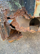
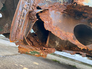
I’ve taken the front wings off that shell you had the rear arch out of Sean; it’s very rusty in that area, but I’ll be there at the weekend and will see what photographs I can take
Re: Front inner wing/sill arrangements
Thanks gentlemen.
Tony those pics are very useful in helping understand how far the baffle plate flange extends. As you can see from the NOS panel not all of it is provided by the panel an assuming yours is original in this area the rest of the flange must therefore be part of the curved panel? It will probably be impossible to determine where the seams are as its so nicely sealed up but the middle picture taken from an angle inboard could help if you had one
Alun any automotive archaeology you can extract from that shell would help enormously, thank you.
Thanks
Sean
- Attachments
-
- 20230413_094443.jpg (193.65 KiB) Viewed 2217 times
1977 1850 HL manual O/D
-
DOLOMITE 135
- TDC Member
- Posts: 122
- Joined: Sun Oct 22, 2006 10:31 am
Re: Front inner wing/sill arrangements
The Sill photos below may hopefully be of some help to allow you to determine the correct geometry of the Bulkhead to Sill assembly.What I can't work out it what the arrangements are from the point of the top of the inner and outer sill should be down over. As far as I can see the inner sill stops short of the outer and is closed off by the curved area of the bulkhead/footwell.
My only assumption is that the curved area of said bulhead must have a deep 90 degree return on that comes forward into the wheel well far enough to allow the front of the outer sill to be spot welded to it before turning another 90 degrees to provide the missing support to the baffle plate from top of the sill to the bottom edge of the wing?
Other Sill pictures here:
https://forum.triumphdolomite.co.uk/vie ... hp?t=33959
- Attachments
-
- Sill top.jpeg (61.59 KiB) Viewed 2186 times
-
- Sill bottom.jpeg (57.51 KiB) Viewed 2186 times
-
- Sill3.jpeg (67.97 KiB) Viewed 2186 times
Re: Front inner wing/sill arrangements
Many thanks for that, corrects my misconception that the inner is slightly shorter than the outer, so the nose of the outer should spot weld to the flange of the inner and the diaphragm.DOLOMITE 135 wrote: ↑Fri Apr 14, 2023 10:46 pmThe Sill photos below may hopefully be of some help to allow you to determine the correct geometry of the Bulkhead to Sill assembly.What I can't work out it what the arrangements are from the point of the top of the inner and outer sill should be down over. As far as I can see the inner sill stops short of the outer and is closed off by the curved area of the bulkhead/footwell.
My only assumption is that the curved area of said bulhead must have a deep 90 degree return on that comes forward into the wheel well far enough to allow the front of the outer sill to be spot welded to it before turning another 90 degrees to provide the missing support to the baffle plate from top of the sill to the bottom edge of the wing?
Other Sill pictures here:
https://forum.triumphdolomite.co.uk/vie ... hp?t=33959
Tony's picture shows there is nothing supporting the baffle in that area so that part of the fog is lifting.
What I still can't work out it where the rest of what I'm calling the baffle flange comes from. You can see there's quite a bit not provided by the panel I have. It appears unmolested and tallies with the sketch in the parts book so I think it's all present and correct.
It can only be part of the curved panel, or a specific insert provided for that purpose?
Thanks for all the responses so far, much appreciated!
Sean
1977 1850 HL manual O/D

Re: Front inner wing/sill arrangements
Perfect Tony! Many thanks, that answers the question largely. You can see there are effectively two flanges, most of which seem to originate from the curved panel rather than the panel I have, you can see the flange that it provides sitting behind at the top.
Really helpful, appreciate the support, thank you!
Sean
1977 1850 HL manual O/D
-
xvivalve
- TDC West Mids Area Organiser
- Posts: 13568
- Joined: Thu Sep 28, 2006 1:13 pm
- Location: Over here...can't you see me?
Re: Front inner wing/sill arrangements
Probably not a lot of help, but…


Re: Front inner wing/sill arrangements
You weren't wrong when you said it was rusty Alun!
There is actually some useful information in those pics many thanks for talking them.
Sean
1977 1850 HL manual O/D