24 years restoring a Sprint in New Zealand

Restoring your car? Tell us about it here!
Message
Author
User avatar
sprint95m
TDC Member
Posts: 6503
Joined: Thu Aug 09, 2007 1:22 pm
Location: Caithness, Scotland

Aye.............

#106 Post by sprint95m »

Congratulations Robert :D .

There is always some minor stuff to sort out once you put a car back on the road, 'tis part of the fun.


Ian.
TDC Forum moderator
PLEASE help us to maintain a friendly forum,
either PM or use Report Post if you see anything you are unhappy with. Thanks.
Jon Tilson
Guest contributor
Guest contributor
Posts: 11179
Joined: Tue Oct 03, 2006 9:45 pm
Location: Middlesex

Re: 24 years restoring a Sprint in New Zealand

#107 Post by Jon Tilson »

As Stu says you need to make sure the rubber bushes at the top the the shock mount are compressed even when teh spring is off load.

I'm sure you can figure out a way of doing this by taking the spring load off with spring compressors. Some dished washers have a lip which should locate inside the hole in the top plate. The shock "plunger" should have a flat section at the top so you can hold it still with a 1/4 opne ender while tightening the nuts. Think Ive probably just repeated what Stu already said...:-)

Other than that let me add my congrats to an enthralling resto...nearly there now and time to enjoy.

Jonners
Note from Admin: sadly Jon passed away in February 2018 but his humour and wealth of knowledge will be fondly remembered by all. RIP Jonners.
User avatar
Toledo Man
Guest contributor
Guest contributor
Posts: 7542
Joined: Tue Oct 03, 2006 5:52 pm
Location: Halifax, West Yorkshire
Contact:

Re: 24 years restoring a Sprint in New Zealand

#108 Post by Toledo Man »

The top plates are angled on some Dolomites (check out mine & Stu's resto threads) which might explain the rattiling. Somebody had posted a thread on this subject about 4 years ago and it just so happened that I was replacing Brown's rear spring & shockers at the same time so it came in handy for me.
Toledo Man

West Yorkshire Area Organiser
Meetings take place on the first Wednesday of the month at 8.00pm at The Railway, 1 Birstall Lane, Drighlington, Bradford, BD11 1JJ

2003 Volvo XC90 D5 SE (PX53 OVZ - The daily driver)
2009 Mercedes-Benz W204 C200 CDI Sport (BJ58 NCV - The 2nd car)
1991 Toyota Celica GT (J481 ONB - a project car)
Former stable of SAY 414M (1974 Toledo), GRH 244D (1966 1300fwd), CDB 324L (1973 1500fwd), GGN 573J (1971 1500fwd), DCP 625S (1977 Dolomite 1300) & LCG 367N (1975 Dolomite Sprint), NYE 751L (1972 Dolomite 1850 auto) plus 5 Acclaims and that's just the Triumphs!

Check my blog at http://triumphtoledo.blogspot.com
My YouTube Channel with a bit of Dolomite content.

"There is only one way to avoid criticsm: Do nothing, say nothing and BE nothing." Aristotle
Robert 352
Guest contributor
Guest contributor
Posts: 389
Joined: Tue Sep 25, 2012 2:08 am
Location: Christchurch, New Zealand

'Tis part of the fun!!

#109 Post by Robert 352 »

Would the person who borrowed my spring compressors now kindly return them!

I guess that is one of the penalties of producing a couple of sons who like their father seem to enjoy tinkering with motor cars. Both though deny any knowledge of having borrowed my spring compressors. I will have to borrow some today and then look to buy another set.

The rubber bushes at the top of the shock mount are fully compressed, although with when installed in the car and the weight of the car is compressing the rubber bushes on the underside of the top plate, they certainly do not look fully compressed. I shall dismantle the assemblies, when I can find a set of spring compressors and examine further.

I remember that one of the very early articles in the DSR News, that is before the internet (can anybody remember what life was like before the internet?) was about the correct orientation of the top plates and the angled rubber mounts. My shock absorbers were installed exactly as suggested.

I think the problem is likely to be that the rubber bushes have passed their use by date! I shall report in due course.

Two other problems came to light yesterday one of which caused a real panic.

The windscreen wipers, which I installed only minutes before I set off for my WOF inspection parked 180 degrees out from where they should sit. I suspect that I have mounted the crank on the wiper motor 180 degrees out of position. I suppose I had a 50% chance of getting it right/wrong!! Fortunately Paul the examiner accepted that I would have to take the instruments out in order to get access to the back of the wiper motor and be able to see what needs to be done and change it. It is a job that will have to be done before I deliver the car back to him on Monday.

The overdrive did not operate either. I checked the two switches, for the reverse light operation and overdrive that mount on the gearbox before I installed them on the gearbox and resoldered and resleeved the connectors which go on the back of the overdrive switch on the gearlever but I have a sneaking suspicion that it might be the overdrive switch itself which is not switching. It could of course be the overdrive solenoid or even the overdrive itself. Give me time and we will sort it.

And I still have to fit some of the exterior trim. The front spoiler is not on yet. I left it off because of the need to have clear access removing and fitting the engine/subframe from underneath. And I have not yet fitted the exterior trims on the C pillars either hoping that I might find a couple of better ones than the two I have here. I shall fit what I have and if something better turns up then change them later.

As Ian said “‘tis part of the fun”. Well I want to do as Jonners says, just get out and enjoy the car. And I need the space in the workshop to move one of my other cars in and carry out some long deferred maintenance.

Time to get back out into the workshop. It's going to be a cool 23 degrees here today.

Robert
Robert 352
Guest contributor
Guest contributor
Posts: 389
Joined: Tue Sep 25, 2012 2:08 am
Location: Christchurch, New Zealand

50 miles of motoring!

#110 Post by Robert 352 »

When that heading reads 50 thousand miles of motoring I will know my effort was worth it.

I drove the car down to our nearest village yesterday, some 8 miles away, to fill with petrol, and ran out on the way. It was a bit disconcerting I must admit but I had a container of petrol in the car, just in case. I drove the car into the engine reconditioner's on the way back here so that they could see the results of their work and note that it was not all in vain.

I spent a few days down in the Southern Alps last week and I dare not show some of the photos I took for Ian thinks it is not fair to do so. Brilliant summer days while I was away, while the northern hemisphere puts up with their winter weather. Some lovely views of the peaks in the mountains.

While I was away the mechanic, Paul, who checked the car for its WOF aligned the steering and adjusted the float levels in the carbs and checked the work which I had done. The car has a tendency to run on after the ignition is switched off but we have now brought the static timing back to about 5 degrees and reduced the idle speed. He pronounced the carbs to be in good condition.

I took the shock absorbers out of the rear of the car over the weekend and at Stu’s suggestion checked, the cupped washers that came with the Koni D adjustable shock absorbers and which sit either side of the mounting plate. The shoulder which sits in the hole measured about 1/8 of an inch.
20130204-3991Ptw Koni bush holders.jpg
20130204-3991Ptw Koni bush holders.jpg (117.47 KiB) Viewed 3903 times
With the two stacked together as seen here they were moving around inside the mounting plate creating an alarming rattle.

I have removed one of the two on each shock absorber and replaced them with what was on the car previously. The rattle has gone.

I have replaced the overdrive switch which was the reason why I could not engage the overdrive. That now works. Another couple of tasks crossed off the list.

However in the drive back from putting in the petrol, the viscous fan coupling started to protest. I have now searched this Forum and read through 14 pages of references on viscous fans and know that it is time to pull this one off and replace it. I have one spare in stock but it has a three bolt rather than a four bolt attachment onto the timing cover. The odd thing is that my copy of the parts book, June 1974, shows it as a three bolt connection although further down the page it states that four bolts are required.
20130205Pw Timing cover.jpg
20130205Pw Timing cover.jpg (115 KiB) Viewed 3903 times
I shall pull the radiator off and try it! I hope it will fit. If it does and is not satisfactory then I will fit an electric fan of some sort.

Other problems? Yes there are other things which will have to be attended to. The steering feels a little vague. I did not touch the rack before reinstalling it.

And there is some bearing whine from the rear axle area. Which to be honest does not surprise me. Most of you will have seen the photos of the car at the commencement of this thread. It is the same back axle in the car which carried the load of the wall which crushed the rear end of the car. I expect the wheel bearings will need to be changed at some stage. I have a spare axle here from a Sprint which was destroyed in a fire. I may have to rebuild it and fit it.

Robert
Dolly-Nut

Re: 24 years restoring a Sprint in New Zealand

#111 Post by Dolly-Nut »

Fans can be changed carefully with the rad in.
And static timing shouldn't really need to be below 10deg on anything 95RON or over, power will drop.
Robert 352
Guest contributor
Guest contributor
Posts: 389
Joined: Tue Sep 25, 2012 2:08 am
Location: Christchurch, New Zealand

Temporary fan installed.

#112 Post by Robert 352 »

Thanks Dan for that tip.

I suspect that the viscous fan I removed from the car today was about to attempt an escape through the radiator. It was exhibiting signs of a major wabble. My spare also has movement in it. So as a temporary measure I have fitted a fan from an 1850. The car is not going to get a great deal of use in the short term.

Geoff/gmsclassics has recommended a suitable electric fan which is available here in New Zealand and he recommends a Revotec electronic fan control which we will have to bring in from the UK.

Yes I managed to get the fan out and the replacement in without taking the radiator out loosing skin on one knuckle only. And without marking the radiator either.

Robert
straylight

Re: 24 years restoring a Sprint in New Zealand

#113 Post by straylight »

Image

yup, one look at those cupped washers and I thought, "snap". Good diagnosis.

I could probably spare you a viscous coupling Robert, or see classic and race as I think they have some.

good news all round really. Problems being solved, car being run, enjoyment being had :)

can you let me know how you went about setting the float levels. I need to do that on mine.

and bugger Ian, lets see the pics of hobbit country :D

(sorry Ian, you know I live vicariously through scenic photos)

stu
Jon Tilson
Guest contributor
Guest contributor
Posts: 11179
Joined: Tue Oct 03, 2006 9:45 pm
Location: Middlesex

Re: 24 years restoring a Sprint in New Zealand

#114 Post by Jon Tilson »

Great stuff Robert
and you could always post a url to a photbucket style location.
Ian doesnt have to look at it then...:-)

Jonners
Note from Admin: sadly Jon passed away in February 2018 but his humour and wealth of knowledge will be fondly remembered by all. RIP Jonners.
User avatar
Toledo Man
Guest contributor
Guest contributor
Posts: 7542
Joined: Tue Oct 03, 2006 5:52 pm
Location: Halifax, West Yorkshire
Contact:

Re: 24 years restoring a Sprint in New Zealand

#115 Post by Toledo Man »

I second what Dan has said about the fan. I had the one on my Sprint let go. Fortunately, it happened when I was pullng out of a junction and I wasn't far from home so I was able to get back. I ended up fitting a secondhand fan assembly and I was able to swap it without removing the radiator.
Toledo Man

West Yorkshire Area Organiser
Meetings take place on the first Wednesday of the month at 8.00pm at The Railway, 1 Birstall Lane, Drighlington, Bradford, BD11 1JJ

2003 Volvo XC90 D5 SE (PX53 OVZ - The daily driver)
2009 Mercedes-Benz W204 C200 CDI Sport (BJ58 NCV - The 2nd car)
1991 Toyota Celica GT (J481 ONB - a project car)
Former stable of SAY 414M (1974 Toledo), GRH 244D (1966 1300fwd), CDB 324L (1973 1500fwd), GGN 573J (1971 1500fwd), DCP 625S (1977 Dolomite 1300) & LCG 367N (1975 Dolomite Sprint), NYE 751L (1972 Dolomite 1850 auto) plus 5 Acclaims and that's just the Triumphs!

Check my blog at http://triumphtoledo.blogspot.com
My YouTube Channel with a bit of Dolomite content.

"There is only one way to avoid criticsm: Do nothing, say nothing and BE nothing." Aristotle
Robert 352
Guest contributor
Guest contributor
Posts: 389
Joined: Tue Sep 25, 2012 2:08 am
Location: Christchurch, New Zealand

Summer time!

#116 Post by Robert 352 »

So far it has been a glorious summer and it seems we will go on enjoying it for a while longer. So the restoration project stopped for a week or more as I headed down to one of our Alpine villages to help with the felling and removal of some very mature Douglas fir trees some of which were close to 100 feet tall. It was time to don all the safety equipment, sharpen the big chain saw and drop them to the ground.

There resided in the village a fine collection of classic vehicles from the 1940’s and 1950’s. I will take the Sprint down in due course where it can sit midst a gathering of Alvis’s, Riley’s and Jaguar’s. And an early Landrover.

Back in November I struggled a little to get the left hand stainless gutter trim on. Today it was the turn for the right hand. We have to make do here with what we have and I have had to make do with a fairly well twisted trim which seemed to polish up reasonably well on the polishing buff. This time I found that the only way to fit it correctly was to adopt the suggestions made by Steve and Jereon back in November last and I installed it from the bend. I did try from the windscreen bottom but I started too low and it did not reach past the end of the gutter rail.
20130222-4033Ptw HU5000 Fitting the trim.jpg
20130222-4033Ptw HU5000 Fitting the trim.jpg (113.81 KiB) Viewed 3799 times
I clamped it as I had done earlier although it was hardly necessary for this one seemed to push down and clip over the bottom lip relatively easily but for those of you who find it a bit of a struggle then clamping and tapping with something soft might be the way to go.

I have now fitted the two C pillar covers and all the trims around the back window. I have not glued the covers into place for they are quite badly marked and I hope that I will find a couple of better ones in due course. The stainless trims buffed up pretty well and the final job was to work a little Dum Dum along the join line between the vinyl roof and the stainless trim itself.
20130222-4035Ptw HU5000 Roof detail.jpg
20130222-4035Ptw HU5000 Roof detail.jpg (114.63 KiB) Viewed 3799 times
I have caulked this join line up for I want the water running off the roof to run over the trim rather than to find its way under the trim and perhaps find its way back under the vinyl. Rust is generally not a problem here but I have seen rather horrid photos on this forum of rust in the rear of the roof.

I have used a lot of Dum Dum in the course of this restoration along join lines like this one, on the front doors in order to keep water out of the door inners.
20130222-4036Ptw HU5000 Door detail copy.jpg
20130222-4036Ptw HU5000 Door detail copy.jpg (117.1 KiB) Viewed 3799 times
One thing that I do miss is that I do not have an exterior door mirror and I need to find something that I can mount on the driver’s door which suits a car of the mid 1970’s. I am open to suggestions.

I have changed the float needles and their seats this week also and my next job will be to set the carburettors up properly.

The photos taken above show the car sitting outside and shows that the car needs a good wash and polish after sitting inside for so long. It will be washed shortly but the polish will have to wait for there are a few marks in the paintwork which need touching up before I can apply that first polish.

It is time to head back out into the sunshine. It is time too to fell a couple of really large, but dead gum trees, saw them up, split them and stack them away for our winter heating. There can be nothing nicer than sitting in front of log fire on a cool winter's evening.

Robert
User avatar
Mad Mart
TDC Member
Posts: 8532
Joined: Tue Oct 03, 2006 5:48 pm
Location: Winscombe, North Somerset, England
Contact:

Re: 24 years restoring a Sprint in New Zealand

#117 Post by Mad Mart »

I usually buy these mirrors for my resto projects...

http://www.ebay.co.uk/itm/CLASSIC-MGB-M ... 5d32dc68ca
Sprintless for the first time in 35+ years. :boggle2: ... Still Sprintless.

Engines, Gearboxes, Overdrives etc. rebuilt. PM me.


2012 Porsche Boxster 981 S


Image
Robert 352
Guest contributor
Guest contributor
Posts: 389
Joined: Tue Sep 25, 2012 2:08 am
Location: Christchurch, New Zealand

Another job crossed off the list

#118 Post by Robert 352 »

Well there have been several little jobs done this week although the first one is really a job in progress.

Jeroen has pointed out that with the front carburettor sitting ever so slightly higher than the rear one that it is important that the float levels be set correctly. On one of his other postings he mentions that by pulling the choke fully out, when the carburettor tops have been removed the fuel level should coincide with the top of the jet.

That has not been the case in my car, so far! And another little trick that has been shown to me is that if you blow a puff of air down on the jet you will see the fuel level drop and rise up again. It is called the puff test here.

On my front carburettor the fuel has almost been spilling over the top and running down the inlet manifold. So this week I fitted new float needles and fiddled around adding extra sealing washers under the float valve casing trying to get the level to drop to match the rear carburettor, which when fitted with the new float valve and a very thin sealing washer was sitting too low. I now have a combination of old and new float valves fitted but the front is still too high and it does not match the rear. I would really like it the other way round.

So it is work in progress, still work to do before I follow Jonners instructions to the letter and find that sweet spot in the idle setting.

I have done 125 miles now since I started the engine so I re-torqued the head down this week. Backed each stud/bolt off a quarter turn and then retightened to 60 ft/lbs. Cam cover gasket is now fitted with gasket sealant.

The rear gearbox oil seal was leaking badly. I found amongst my stock of spares a new gearbox oil seal NKC39A dated 1989. Still in its sealed packet. It was a nice day here, in fact it has been a superb summer so far with no rain really since early December. So I drove the car up onto the ramps which sit outside the workshop and sat underneath out of the sun and removed the prop shaft and the nut on the back of the gearbox.
20130302-4048Ptw HU5000 On the ramp.jpg
20130302-4048Ptw HU5000 On the ramp.jpg (126.88 KiB) Viewed 3748 times
I find I am spending as much time on these little jobs making the necessary tools, in this case the arm which I bolted to the flange to allow me to both undo the nut and retighten it correctly when I finished. It was very pleasant working under the car today. Plenty of room and plenty of light. Can somebody though tell me what are the functions of all those additional holes in the various cross members and inner sills for. I have marked one here.
20130302-4042Ptw HU5000 Gearbox rear seal replacement.jpg
20130302-4042Ptw HU5000 Gearbox rear seal replacement.jpg (106.22 KiB) Viewed 3748 times
Should they be fitted with grommets to keep the moisture out?

Then another little job was completed. I had earlier made up my relay pack for the headlamps but because I have fitted quartz halogen lamps to the car which have single filaments, the dip beam was not staying on when I selected high beam. So I have added another relay to the pack which when high beam is selected allows the dip beam to remain on.
20130302-4053Ptw HU5000 relay arrangement.jpg
20130302-4053Ptw HU5000 relay arrangement.jpg (61.82 KiB) Viewed 3748 times
Some have commented about my positioning of the relays, that they might well be in the direct line of the all that comes through the front grille. They are largely protected by the front valance and by the side of the radiator. They are also sealed relays. I will if necessary add a shroud to keep the water off.

The big plus for me is that the relays are as close as it is practical to get them to the lights and just as importantly there is no additional clutter in the engine bay itself. Everything looks neat and tidy.

I noted one thing though. The wiring diagrams in the workshop manual and in the owner’s handbook are more a sort of schematic for they do not show how the headlamp flasher switch is connected to the headlamps. No wiring shown at all. Which is a pity really for when I originally turned the headlamps on to the dip beam and pulled the headlamp flasher on all four headlamps came on. I cannot see how that happens I cannot see where or how that flasher is connected at all. It certainly happens now with the fitting of the third relay.

Robert
Robert 352
Guest contributor
Guest contributor
Posts: 389
Joined: Tue Sep 25, 2012 2:08 am
Location: Christchurch, New Zealand

Fixing oil leaks again

#119 Post by Robert 352 »

There are various proverbs about making haste and repenting at leisure, it’s not quite what I had in mind in describing what has happened over these last couple of weeks since I added my last post. But in taking a short cut, or in my case neglecting to do the obvious, I have had to go back and redo some tasks which I had done earlier. I will describe those tasks in a moment.

I mentioned in my last post that I had changed the rear gearbox seal in order to cure a leak. It did not fix the problem! The leak remained, and it is, or hopefully was, quite a substantial leak. And I only found the cause of the leak because I was trying to sort out my carburettor problem.

I had sent private messages to both Jeroen and Jonners seeking their advice on how I might solve the problem of different float levels in the two carburettors. Jonners made what was an interesting suggestion. Check the rear gearbox mount just in case it has dropped significantly. Jeroen made the point that he did not think that a pronounced sag in that mount would alter the angle at which the engine sits sufficiently to upset the float levels.

But I went ahead and checked the gearbox mount for sometimes it is something which causes a problem elsewhere. And it is very easy enough to do. I put the car up on the open air ramps again and removed the gearbox mount. It was covered in oil but was intact and had or was not allowing the back of the gearbox to drop significantly. Once I had removed that mount though I discovered the source of the gearbox oil leak for when I looked up I could see over the top of the overdrive unit and see where oil was dripping off one of the selector rods. That oil was cascading down over the rear of the overdrive unit and it was that oil which caused me to think that the rear seal had failed.

My only course of action then was to remove the passenger seat, disconnect the handbrake onto one of the rear drums, remove the front carpets and then remove the gearbox cover. Once the cover was removed I then took the top cover off the gearbox, yes the workshop manual says you can do this, without removing the parcel shelf, which was a bit of a plus.

There was a lot of oil visible where the three selector rods come out of that cover. The rods are sealed by three o-rings which are held in place by plate and which is only accessible by removing the selector rods themselves. I had earlier broken the top cover on my gearbox and bought another complete gearbox which I suspect had been sitting outside and left standing on its bell housing. There was evidence that there had been quite a lot of moisture in that donor box. I cleaned the cover of course, and reinstalled the selector rods which were in the cover which I had broken for they were in much better condition than those in the donor box.

But I neglected to do two things.

Firstly I did not fit new o-rings, (I purchased three today for about 35 pence each). But why was the oil coming out past those o-rings? I figured that the gearbox must heat and cool as it is used and there must be some sort of breather somewhere and that perhaps this breather was blocked. If it was blocked then the build-up in pressure within the gearbox was perhaps sufficient to force oil out past any one or all three of these o-rings, which are only held in place very lightly by their cover plate. I found the breather hole right at the front of the top cover, as marked.
20130312-4061Ptw HU5000 Gearbox cover.jpg
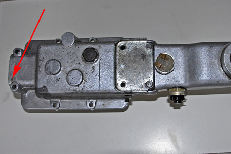
20130312-4061Ptw HU5000 Gearbox cover.jpg (135.75 KiB) Viewed 3700 times
Of course with the donor gearbox standing on its end this little hole seemed to be blocked for when I blew it out with compressed air there was a little wad of muck released.

The second task is that I should have blown it out when I cleaned the cover originally.

It is easy to be wise after the event. But I hope this will lead others to check, if they have their gearbox apart that this little hole is clear. It sits forward of the end of the reverse selector rod and I imagine that there is sufficient clearance, and fairly minimal movement to allow the internal space within the gearbox to breathe, and which allows air to pass along that selector rod and not allow the oil which might follow, to escape.

I shall report shortly on whether I have fixed the problem when I have replace the gearbox cover, refitted the gearlever, reconnected the handbrake and driven the car. But I can say that when I ran the engine with the car in neutral and the gearlever out before I took the top cover off the gearbox I could see the oil drips forming below the o-ring cover plate. It has not done so since I have put everything back together.

With the cover off from around the gearbox, and with the front carpets removed I shall attend to another little task and that is to remove some spacers from behind the exhaust shield which sits on the firewall/bulkhead. I fabricated my own exhaust shield for mine has been lost in the 24 years since I stripped the car out. I spaced it well off the bulkhead to allow air to circulate behind it but I notice that occasionally the engine rocks sufficiently to allow it to touch.

At this point perhaps I should make a comment about this exhaust shield and how I have discovered that making it possible to unbolt allows me to remove the cylinder head off the engine in the car without any drama at all.

Others have commented in other threads on this Forum about the need to say a prayer or two if it becomes necessary to remove the cylinder head off a Sprint when the engine is still in the car. The problem it seems is the removal of the exhaust downpipe at the back of the exhaust manifold. I have retained the three original studs on my exhaust manifold. When I fabricated a copy of the heat shield which sits on the engine bulkhead I chose instead to bolt it to the bulkhead rather than pop rivet it.

Twice now I have removed the cylinder head with the engine in the car and in both cases the easiest way to remove the exhaust downpipe was to unbolt the heat shield first and remove it and then unbolt the exhaust downpipe.

Unless I am very much mistaken the fitting of all the exhaust heat shields probably came after the prototype cars were developed, and was perhaps not thought necessary in the original design. However after the car had been developed the heat shield in question was fitted to overcome a heat build-up in the passenger side of that bulkhead. It was very easy to pop rivet the heat shield onto the bulkhead during assembly but in doing so those who formulated the instruction to rivet the heat shields in place forgot that this technique possibly made it very difficult to remove the exhaust downpipe at some later stage.

I rather imagine that it would have never been a problem in the factory for if like the car which I have been rebuilding there was a problem with the engine or its transmission at the end of the assembly line the whole car assembly was probably moved into some form of remediation area where the complete sub-frame assembly was removed and a spare fully assembled engine sub-frame assembly substituted. It would have taken no longer than 90 minutes to make the change and this process would have helped the production team to achieve the targets set of so many cars coming off the line in any nominated period.

Faulty engines, gearboxes or clutches would have possibly been put right in this remediation area and would have been held waiting for the next sub frame change if and when it was needed. There would have been no need to remove exhaust downpipes using this technique, so there would have been no need to remove the heat shield and the problem would not have been noted by the designers.

I am learning as I go along. The spacing of that heat shield is tight for there is not much room and I could only guess how far to space it off the bulkhead when I installed it originally. And I am learning that not installing new o-rings which have minimal value was false economy too. Just as neglecting to blow out that small breather hole on the top of the gearbox has caused me to go back and redo the job properly this time.

I suspect that at some stage, if my returning of this car to the road continues in the way it has then perhaps I too will be able to claim like Jonners that “If I haven't done it in or to a dolomite....”! I hope not for I want to use the car now and wear it out before it wears me out.

Nobody so far has been able to answer my query on whether I should fit grommets to the holes in the underside of the car, one of which I marked in my previous posting. And nobody either has commented either on the lack of detail in the wiring diagram.

How does the headlamp flasher switch connect to or where does it connect to the high beam circuit?

Finally on a much more positive note. I spotted 2drToledo/Jim’s offer of a Stainless Steel and Chrome O/S door mirror which he is offering for sale. Jim was very prompt in answering my queries and obtaining a quote to post it to New Zealand. Mad Mart has also given me the name of a possible mirror supplier. In the meantime though I have unearthed a couple of black painted mirrors which were sold in the early 1980’s and my thinking now is to fit one of those on the off side door of my car. So I thank Jim here for the effort he went to on my behalf and hope that his mirror will find a good home elsewhere.
Last edited by Robert 352 on Wed Mar 13, 2013 9:00 am, edited 1 time in total.
User avatar
gmsclassics
TDC Member
Posts: 670
Joined: Fri Oct 06, 2006 9:57 am
Location: Auckland, New Zealand

Re: 24 years restoring a Sprint in New Zealand

#120 Post by gmsclassics »

Hi Robert

Been away for a while so only just catching up.

My reading of the wiring diagram is that the connection for the headlamp flasher to the main beam is internal to the switch and uses the same wires. The only difference is that the source of power is not from the master light switch (blue wire) but from the horn switch (purple). The way the connections work internal to the dip/main/flasher switch ensure that current can't feed incorrectly.

Not sure about the chassis holes, will have to wait until I have the car in the air again. I have a feeling that mine are open like yours but I should confirm that. Nothing in the parts catalogue I can see.

I got all of my replacement mirrors (black and chrome door and wing mirrors from Rimmers, They are TEX brand and have been fine.

By the way I will hopefully get my replacement / hardened / re-ported head back in a few days!

Geoff
Post Reply