Hi everyone,
While i'm waiting for the parts to fix my brakes, I thought I could start fixing the electrics.
This is probably going to take a while as there isn't much working properly , so i'll just go step by step,
I thought i'd start with the temperature gauge which doesn't seem to be very lively ( mind you I never left the engine running for longer than 15min, so maybe its normal).
I read to check it what I want to do is, disconnect the cable attached to the sender unit and make that cable touch the engine, is that correct?
Thanks
If it doesn't your voltage stabiliser situated above the fusebox could be faulty. You can get a solid state voltage stabiliser or make your own, lots of examples on this forum, I made my own, it is somewhere in the pages of the MSO 662P thread.
Also worth cleaning all the connections to the fusebox & the fuse connections.
Thomas
Both the temperature gauge and the fuel gauge are controlled by the voltage regulator - a good indication that the regulator is faulty is that the fuel gauge needle will rise to the quantity if fuel within the tank - then start to drop back to zero - you will see the needle moving back to zero.
Are you any good with a soldering iron as I purchased one these http://www.ebay.co.uk/itm/351026317555? ... 1436.l2649
and replace the semi conductor, you dont need the middle terminal as this is an additional earth, the semi conductor is earthed via a small self tapping screw within the regulator housing.
tarynus wrote:It rises, but not fully, only goes half the way... What does that mean?
Unless there's a bad connection, the voltage regulator is faulty. This is the most likely scenario.
As Paul says, buy a 7810 voltage regulator (buy a couple, they're pennies and getting harder to find) connect it up in place of your voltage stabiliser, job done.
Further to what has been said Thomas,
a more general point is that you should look at all the wiring earths.
A bad earth can give some interesting (as in unlikely) readings on the gauges.
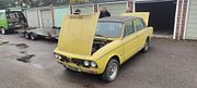
On the yellow T2500 I owned, turning the lights on made both the temperature and fuel gauges read higher
and made the oil pressure gauge reading drop (to below zero at idle speed ). Turned out that a poor earth
was at fault for the first two gauges but the oil pressure gauge continued to have a mind of it own.
Ian.
TDC Forum moderator PLEASE help us to maintain a friendly forum,
either PM or use Report Post if you see anything you are unhappy with. Thanks.
I'll try taking the voltage stabilizer and fixing it if it s possible.
Before i do so, is it possible to check if its working properly or not with a multimeter (not sure this is the right translation, maybe its called a tester?).
Also how do you check for bad earth?
Yes i'm even worse at electrics than mecanics!
Oh also my rear lights(maybe its the brake lights) turn on on their own, once the ignition is on. Could that have anything to do with it?
To check the earthing points, it is simply a case of ensuring these are clean and secure.
Undo each in turn and make sure the contact surfaces are nice and shiney.
Regarding the brake lights, I reckon the the switch is the problem, it is either stuck or more likely badly adjusted.
This switch is mounted onto a bracket quite high up behind the brake pedal. Said switch is white in colour and has a push button operation.
If it is stuck it may well free out.
Ian.
PS multimeter is the correct term .
TDC Forum moderator PLEASE help us to maintain a friendly forum,
either PM or use Report Post if you see anything you are unhappy with. Thanks.
You have 3 types of circuit. Two are fused. There is a color code.
Most problems start at the fuse box with dirty contacts either on the fuse or holder or the lucar spade connectors to the fuse box.
Take the fuse box off and give it a good soak in something like Bilt Hamber DeOx and it will come up like new.
The Brown wires into the fuse box are permanent live - not via the ignition switch. The purple wires with tracers come out and do the horn
hazard and interior lights and cigar lighter IIRC. The feed to the hazard switch can cause interesting effects with the indicators. The hazard switch
also needs clean contacts.
The white wires into the fuse box are from the ignition switch. The green ones out do the wipers, washer, fan, indicators and instruments and gearbox reverse lights and overdrive. These are all dark green with a tracer.
Then you have the lighting circuits which are red for low current things like side lights and instrument bulbs, and blue with tracers for the headlights. I think its red tracer for dip and white for high beam but I often get that the wrong way round. All earth return wiring is black. So if its a black wire it should go to an earth point from whatever, heater fan, washer pump, horn and light units.
Problems with lights often start at the main light switch which can develop dirty contacts if unused for ages. It has a brown in and a red out for side lights and blue out for headlights.
Its a good idea to clean any earth connector you come across. The one by the battery and on the inner wing is worth doing, also the ones on the back of the side light and indicator units.
A cheap multi meter with a 12V DC range and a resistance range is a very helpful tool.
Bulb holders that have been unused for a while will cause a lot of problems. Clean and wiggle will bring usually them back.
Hope that helps...
Jonners
Note from Admin: sadly Jon passed away in February 2018 but his humour and wealth of knowledge will be fondly remembered by all. RIP Jonners.
tarynus wrote:I'll try taking the voltage stabilizer and fixing it if it s possible.
Before i do so, is it possible to check if its working properly or not with a multimeter (not sure this is the right translation, maybe its called a tester
Yes, it is perfectly possible to check the original type of voltage stabiliser with a multimeter. With the ignition ON, measure the voltage on the input side. This should be approx 12.5V with a good battery. Now this stabiliser works on a bi-metallic principle which means the internal bimetallic strip vibrates rapidly on and of so the " average" value ( RMS to be precise) is 10V. With the multimeter on a d.c range if it responds to voltage changes rapidly you will see the reading move around quite a bit. If you have a True RMS setting this will read 10V if it is working correctly.
Tony.
Thanks a lot John, very instructive (as usual),
Ian, I did spot that white switch the other day thinking it might be the problem, I'll have another look at it or take a picture as I wasn't really sure if it was fitted properly.
I'll get my hands in this weekend and give you some feedback
Thanks
Hi everyone,
i took off the voltage stabilizer to see if that could solve the problem with the water temperature needle stopping half way up.
But I couldnt really tell wether it is ok or not. It did not show any sign of life with the multimeter, but again not sure I did it right. I set the multimeter on 200 v direct current ( the setting that shows 12.5 when mesuring the battery) and tested where the 2 green wires are attached. Also there are a couple of wires here and which are cut (indicators, fan...not really sure what else, or where to start...)Here are some pictures that may help
IMAG0613 (1024x613).jpg (131.48 KiB) Viewed 1635 times
IMAG0615 (1024x613).jpg (103.53 KiB) Viewed 1635 times
IMAG0616 (1024x613).jpg (94.54 KiB) Viewed 1635 times
Also if I need a new stabilizer could you tell where I could one of these, i tried google but wasnt too sure about the results.
Thanks
Tom