Hello all,please bear with my lack of knowledge about my recently bought negative earth 1977 Dolomite 1500 HL. A previous owner told me that the ignition coil as fitted may need to be changed.As I am a bit nearer 82 than 28,a friend said he would do the job.When he asked me to have a look when done,I feel sure that he wired it wrongly.All the cars that I have experienced over the years with negative earth,have the black wire from the points connected to the negative terminal on the coil,but my friend says it should be to the positive.We have not tried to start the car in case its wired wrongly.Could some wise person please say which is correct?
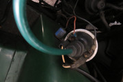
Also there is a small metal cylinder,about 2in x 1 inch just above the coil with 2 wires coming from the loom. The colours are faded,but what looks like green/white goes straight from loom to negative terminal on coil,the yellow/white goes to one of the terminals on the cylinder.A thick grey wire goes from the 2nd terminal on the cylinder to the positive terminal on the coil. Could someone please let me know what is this cylinder? Any advice much appreciated.Joe.
wiring ignition coil

Re: wiring ignition coil
I cannot speak for the specific details of a 1500, but the contact breaker wire most definitely goes to to the negative terminal of the coil, as labeled CB on old coils, and the ignition feed goes to the positive or SW as was. I can see that cylinder in some engine bay shots, can't tell you what it does though, it isn't there on an 1850/Sprint!
Current fleet: '75 Sprint, '73 1850, Daihatsu Fourtrak, Honda CG125, Yamaha Fazer 600, Shetland 570 (yes it's a boat!)
Past fleet: Triumph 2000, Lancia Beta Coupe, BL Mini Clubman, Austin Metro, Vauxhall Cavalier MK1 & MK2, Renault 18 D, Rover 216 GSI, Honda Accord (most expensive car purchase, hated, made out of magnetic metal as only car I've ever been crashed into...4 times), BMW 318, Golf GTi MK3 16v x 3
Past fleet: Triumph 2000, Lancia Beta Coupe, BL Mini Clubman, Austin Metro, Vauxhall Cavalier MK1 & MK2, Renault 18 D, Rover 216 GSI, Honda Accord (most expensive car purchase, hated, made out of magnetic metal as only car I've ever been crashed into...4 times), BMW 318, Golf GTi MK3 16v x 3
-
Richard the old one
- TDC Member
- Posts: 1218
- Joined: Thu Sep 28, 2006 10:06 pm
- Location: Bristol
Re: wiring ignition coil
The Haynes manual states "Ensure that the white/black wire goes to the negative - terminal of the coil and the white/yellow to the positive + terminal."
On my car the wire from the distributer is black and this goes to the - negative terminal on the coil which also has what with what I believe is slate marker. The positive terminal of the coil has a white with yellow marker plus a cable from a cylinder shaped suppressor to stop radio interference.
On my car the wire from the distributer is black and this goes to the - negative terminal on the coil which also has what with what I believe is slate marker. The positive terminal of the coil has a white with yellow marker plus a cable from a cylinder shaped suppressor to stop radio interference.
Re: wiring ignition coil
I'd ruled out the RF choke on the grounds that it has only the one wire, I'm assuming the OP means this thing I've ringed:Richard the old one wrote: ↑Fri Aug 03, 2018 6:45 pm ...plus a cable from a cylinder shaped suppressor to stop radio interference.
- Attachments
-
- Triumph dolomite 1500 hl engine bay cylinder.jpg (132.86 KiB) Viewed 1447 times
Current fleet: '75 Sprint, '73 1850, Daihatsu Fourtrak, Honda CG125, Yamaha Fazer 600, Shetland 570 (yes it's a boat!)
Past fleet: Triumph 2000, Lancia Beta Coupe, BL Mini Clubman, Austin Metro, Vauxhall Cavalier MK1 & MK2, Renault 18 D, Rover 216 GSI, Honda Accord (most expensive car purchase, hated, made out of magnetic metal as only car I've ever been crashed into...4 times), BMW 318, Golf GTi MK3 16v x 3
Past fleet: Triumph 2000, Lancia Beta Coupe, BL Mini Clubman, Austin Metro, Vauxhall Cavalier MK1 & MK2, Renault 18 D, Rover 216 GSI, Honda Accord (most expensive car purchase, hated, made out of magnetic metal as only car I've ever been crashed into...4 times), BMW 318, Golf GTi MK3 16v x 3
-
2door-toledo
- TDC Member
- Posts: 133
- Joined: Fri Apr 13, 2018 11:38 pm
- Location: Berkshire
- Contact:
Re: wiring ignition coil
Is the 'small metal cylinder' the ballast resistor? Although I haven't seen one cylinder shaped...
-
MIG Wielder
- TDC Member
- Posts: 2336
- Joined: Sun Mar 16, 2008 2:52 pm
Re: wiring ignition coil
Yes, this is what I'd expect. Good job you didn't try starting the car with the grey wire and the black wire to the points both on the positive terminal.Richard the old one wrote: ↑Fri Aug 03, 2018 6:45 pm The Haynes manual states "Ensure that the white/black wire goes to the negative - terminal of the coil and the white/yellow to the positive + terminal."
On my car the wire from the distributer is black and this goes to the - negative terminal on the coil which also has what with what I believe is slate marker. The positive terminal of the coil has a white with yellow marker plus a cable from a cylinder shaped suppressor to stop radio interference.
Now I've seen this type of aluminium box with 2 wires coming out used with the very upmarket stereo systems of the 70's. Specifically Blaupunkt. You will probably find " Blaupunkt " engraved on the case if so. It is an in-line interference suppressor choke and is usually used with an interference reducing capacitor fitted from the coil positive to chassis via a self-tapping screw.
And its quite correct that Yellow / white is the supply input and the grey wire goes to the + on the coil.
Did you have a new ballasted type coil fitted ?
The white / slate grey wire goes to the rev; counter btw.
Tony.
-
Rusty47
Re: wiring ignition coil
A big thank you to those who took the time to set me right on the coil wiring, also for the photos which were a great help.I have now changed the coil to a ballasted one.I was curious about that radio interference suppressor as I had never seen a similar unit before.Finally,is there a part number for the capacitor,and what would happen if one was not fitted at all,or not connected to the correct Positive terminal on the coil?Once again,I cant thank you all enough.
-
Richard the old one
- TDC Member
- Posts: 1218
- Joined: Thu Sep 28, 2006 10:06 pm
- Location: Bristol
Re: wiring ignition coil
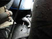
I thought that it might help if I posted a photo of the engine compartment end of the built in ballast resistor. It is just below the water washer container and the three cables that are crimped together come out of the main loom at this point. They are the ballast resistor wire, a wire from the starter solenoid and a wire to the ignition coil. The last two are used to take the ballast resistor out of the circuit when the starter motor is engaged and so provide the higher battery voltage to the ignition coil. This slight voltage overload provides an increased high tension voltage at the spark plugs to improve starting.
Last edited by Richard the old one on Sun Aug 05, 2018 11:05 am, edited 3 times in total.
-
Richard the old one
- TDC Member
- Posts: 1218
- Joined: Thu Sep 28, 2006 10:06 pm
- Location: Bristol
Re: wiring ignition coil
I have only just read the post about the radio interference suppressor. These were not fitted as standard when the cars were built but I assume when most radios were fitted ballast they would have been fitted to stop any interference, hence it is not critical to have one.
Re: wiring ignition coil
You won't need the external capacitor, it's an aftermarket thing to help stop transients causing interference on a radio.
Inside the distributor cap is a 'condensor', old-fashioned name for a capacitor. It's job is to dampen the arcing across the points as they open, don't confuse it with the external capacitor.
It's worth reading how to post photo's on here, a picture can save a thousand words.
Click here -> viewtopic.php?f=4&t=23338